Opposite-clamping pore plate flow quantity adjusting valve

An orifice flow and valve technology, used in sliding valves, valve devices, engine components, etc., can solve problems such as poor flow accuracy control and inability to accurately control high-speed flow, achieve precise adjustment, reduce vibration, and prolong service life. Effect

Inactive Publication Date: 2008-03-19
董映红
View PDF0 Cites 15 Cited by
  • Summary
  • Abstract
  • Description
  • Claims
  • Application Information

AI Technical Summary

Problems solved by technology

At the same time, the valve opening is not linearly proportional to the flow area, so the existing regulating valves have poor flow accuracy control and cannot achieve precise control of high-speed flow

Method used


Image

  • Opposite-clamping pore plate flow quantity adjusting valve
  • Opposite-clamping pore plate flow quantity adjusting valve
  • Opposite-clamping pore plate flow quantity adjusting valve

Examples


Embodiment Construction

[0023] The following examples are used to illustrate the present invention, but are not intended to limit the scope of the present invention.

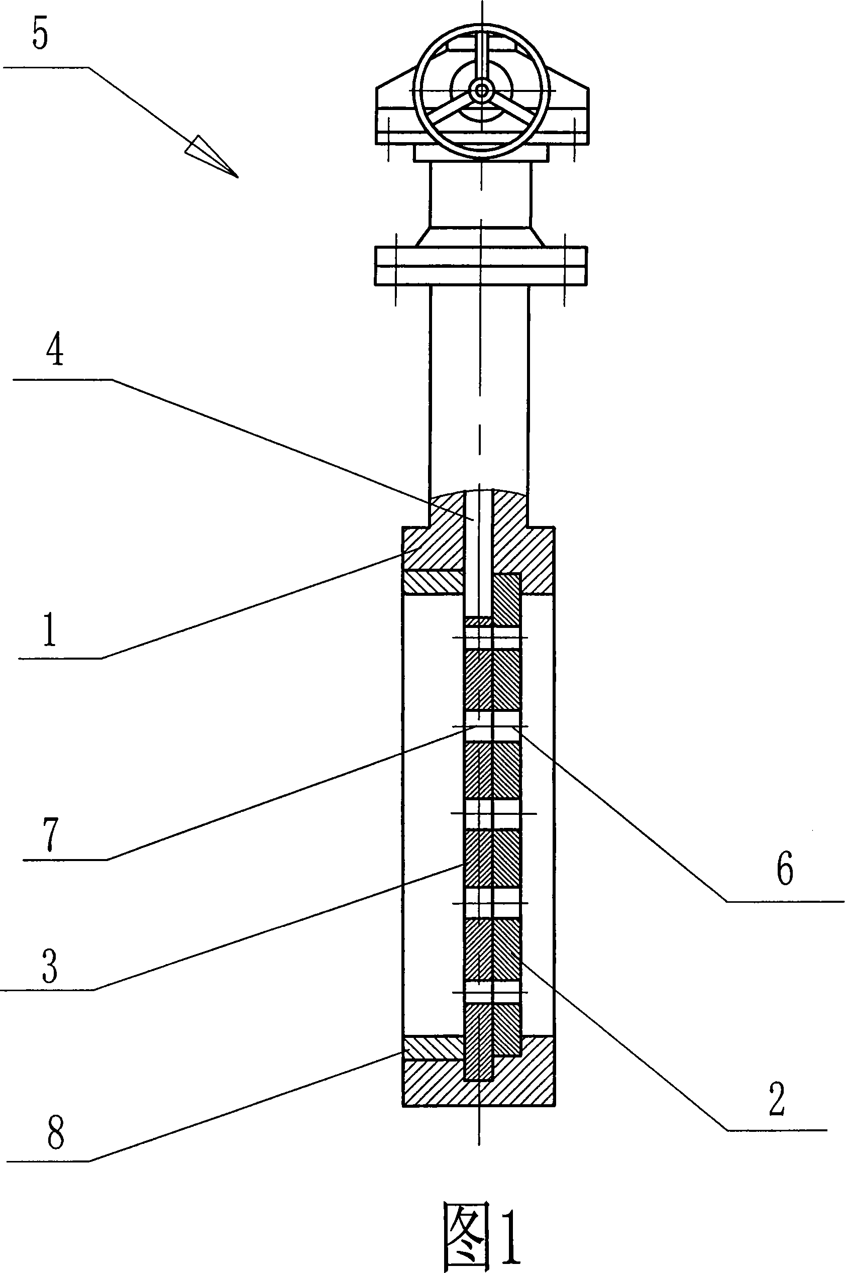
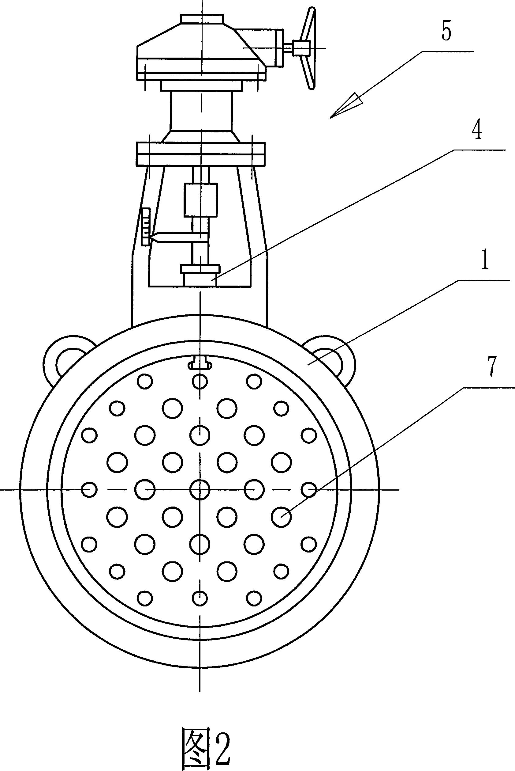
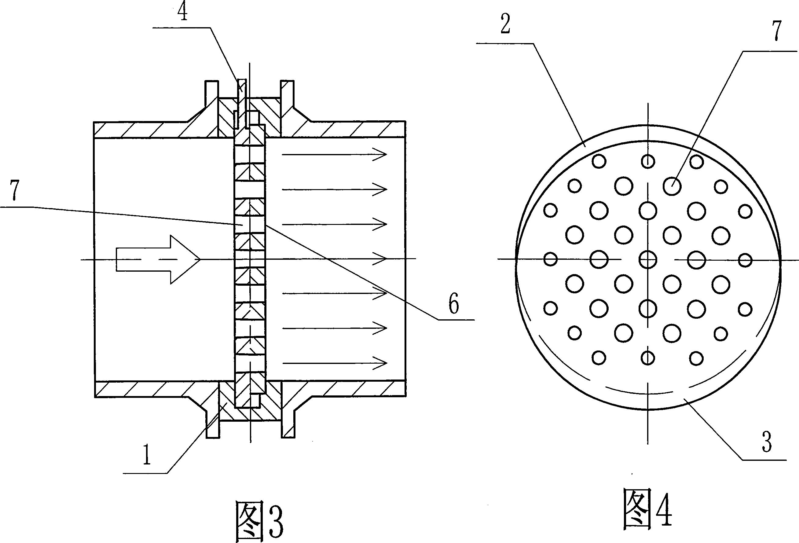
[0024] See Figure 1 and Figure 2. The wafer type orifice flow regulating valve of the present invention includes a valve body 1 , a fixed valve plate 2 , a movable valve plate 3 and an operating mechanism 5 . Wherein the fixed valve plate 2 is fixedly installed in the valve body 1, and the movable valve plate 3 is installed in the valve body 1 so as to move up and down. The movable valve plate 3 is in contact with the fixed valve plate 2. The movable valve plate 3 is provided with a valve stem 4, and the valve stem 4 extends out of the valve body and is connected with the operating mechanism 5. On the side of the movable valve plate 3 close to the inlet, there is a retaining ring 8 for sealing.

[0025] Described operating mechanism 5 can select any existing structure for use, as hydraulic pressure type, pneumatic type, mechanical t...


PUM


Abstract

The invention provides a wafer type orifice plate flow regulating valve, which is used for controlling the flow quantity of a high speed fluid medium, simultaneously can reduce vibration and noise, and can adjust accurately. The invention comprises a valve body, a fixed valve plate and a movable valve plate which mutually contact and match equipped in the valve body, a valve rod arranged on the movable valve, a controlling mechanism connected on the valve rod, a plurality of through holes arranged on the fixed valve plate, and a plurality of over current orifices being able to align the through holes and being arranged on the movable valve plate. The present invention has the advantages that the movable valve plate can be longitudinally moved through adjusting the controlling mechanism, thus the relative position of the movable valve plate and the fixed valve plate is further changed, the flow area is changed, and the parameters of the media flow and the pressure can be adjusted. Because the flow area firmly changes during the movable valve plate opening and closing process, the flow quantity can be accurately adjusted, and because the motion of the medium is straight line motion, the turbulent flow producing is avoided, thus the vibration of the pipe system is effectively reduced, the noise is reduced, and simultaneously the service life of the valve is prolonged.

Description

technical field [0001] The invention provides a wafer-type orifice flow regulating valve which is used for controlling the flow of a high-speed fluid medium, can reduce vibration and noise, and can be precisely adjusted. Background technique [0002] Accurate linear flow regulating valves have always been the development direction of regulating valves. When traditional throttle valves and butterfly valves are used as flow regulating valves, the direction of airflow will inevitably be forcibly changed when the valve is opened because the fluid medium is blocked by the valve plate. Therefore, noise and vibration will inevitably be generated, especially for high-speed flow regulating valves, the noise and vibration are particularly obvious. At the same time, the valve opening is not linearly proportional to the flow area, so the existing regulating valves have poor flow accuracy control and cannot accurately control high-speed flow. Contents of the invention [0003] technic...

Claims


Application Information

Patent Timeline
Patent Type & Authority Applications(China)
IPC IPC(8): F16K3/02F16K3/314
Inventor 董映红
Owner 董映红
Why Eureka
Try Eureka