Engine oil seal lip grease adding device

A filling device and grease technology, applied in the field of fixtures, can solve problems such as high labor intensity, low work efficiency, and poor safety, and achieve the effects of avoiding scratches, low labor intensity, and high work efficiency

Inactive Publication Date: 2008-03-19
CHONGQING LIFAN INDUSTRIAL (GROUP) CO LTD
View PDF0 Cites 8 Cited by
  • Summary
  • Abstract
  • Description
  • Claims
  • Application Information

AI Technical Summary

Problems solved by technology

[0003] 1. The application speed is slow, the labor intensity of the workers is high, and the work efficiency is low
[0004] 2. Uneven application of lubricating grease leads to poor lubricating effect and prone to grease overflow, giving people the illusion of oil leakage
[0005] 3. Unavoidable pollution in manual application
[0006] 4. Since the edge of the lip of the oil seal is sharp, it is easy to scratch the worker's fingers when applying it by hand, and the safety is poor

Method used


Image

  • Engine oil seal lip grease adding device
  • Engine oil seal lip grease adding device

Examples


Embodiment Construction

[0027] Below in conjunction with accompanying drawing and embodiment the present invention will be further described:

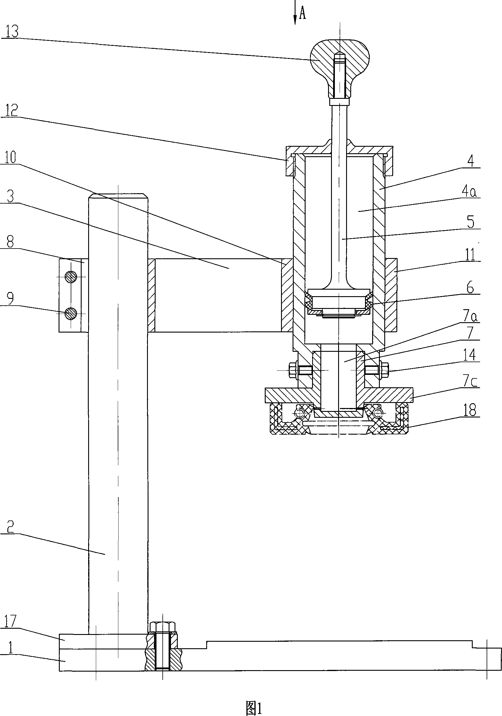
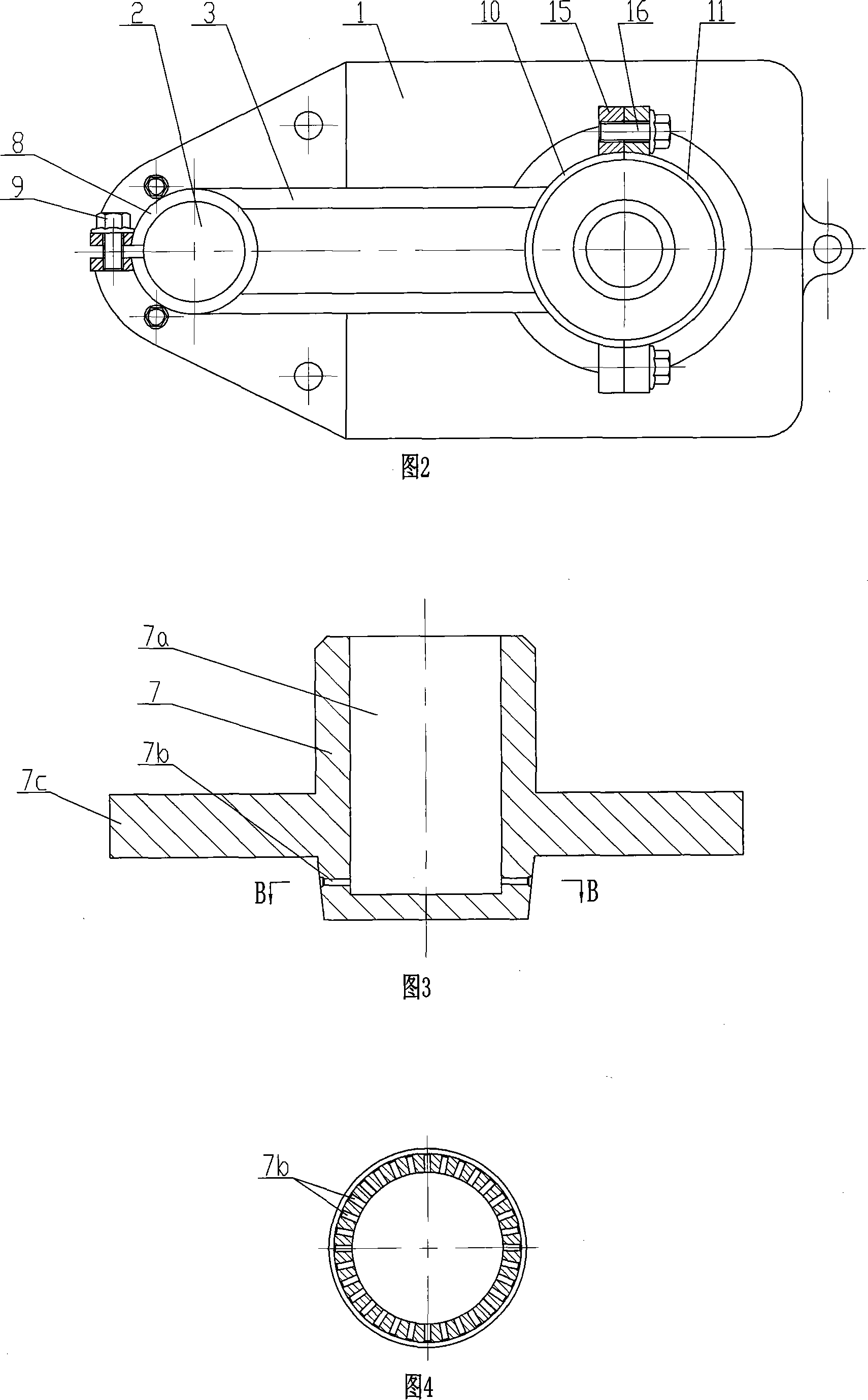
[0028] As shown in Figure 1 and Figure 2, the present invention consists of a base 1, a column 2, a support beam 3, an oil cylinder 4, a push rod 5, a piston 6, a positioning sleeve 7, a hoop 8, a fixed connecting plate 10, a movable connecting plate 11, Parts such as tail cover 12 and bolt constitute. Wherein the base 1 is a flat plate structure, the column 2 is positioned at the side above the base 1 and arranged vertically, the bottom end of the column 2 is a flange 17, and the flange 17 is fixedly connected with the base 1 by screws, and the base 1 can be fixed on work surface. The support beam 3 is horizontally arranged relative to the column 2, and one end of the support beam 3 is welded with a hoop 8, which is set on the upper body of the column 2 and locked by a bolt 9; the other end of the support beam 3 is a cantilever end, located at On the top o...


PUM


Abstract

The invention discloses an engine oil seal lip grease charging device. The bottom part of an upright column is fixed on a bottom seat, a supporting beam is equipped at the upper part of the upright column, and an oil cylinder is fixed at the beam end of the supporting beam; the axle center lines of the oil cylinder and the upright column are parallel, a push rod is arranged in the inner cavity of the oil cylinder, the upper end of the push rod is stretched out the upper end opening of the oil cylinder, a piston is equipped at the lower end of the push rod, and the piston can longitudinally slide in the inner cavity of the oil cylinder; a positioning sleeve is fixed at the bottom end of the oil cylinder, the positioning sleeve with an open mouthed upper end and a sealed lower end is in a cylindrical structure, the inner cavity of the positioning sleeve is communicated with the inner cavity of the oil cylinder, a guiding hole is arranged on the peripheric surface at the lower end of the positioning sleeve, and the guiding hole is communicated with the inner cavity of the positioning sleeve. The invention has good security, and is easy to operate, the grease charging speed is high, the labor intensity of the workers is low, and the operating efficiency is high; the invention can uniformly coat the grease on the oil seal lip, the phenomenon that the grease overflows can not occur, and the erroneous indication of grease leaking is effectively eliminated.

Description

technical field [0001] The invention belongs to the technical field of tooling fixtures, and in particular relates to a lubricating grease filling device for engine oil seal lip, which is used for filling lubricating grease to the lip of the oil seal. Background technique [0002] The crankshaft, oil pump and camshaft oil seals are respectively installed on the corresponding positions of the engine to prevent engine lubricating oil from leaking. In order to effectively prevent the main lip of the oil seal from being scratched and worn, it is generally necessary to apply grease to the lip of the oil seal before assembly. The traditional smearing method is manually carried out, that is, the worker scrapes up a small piece of grease with his fingers, and then strives to evenly coat the surface of the oil seal lip. This manual smearing method mainly has the following shortcomings: [0003] 1. The smearing speed is slow, the labor intensity of the workers is high, and the work e...

Claims


Application Information

Patent Timeline
IPC IPC(8): F16N3/12
Inventor 李中友张志发
Owner CHONGQING LIFAN INDUSTRIAL (GROUP) CO LTD
Why Eureka
Try Eureka