Register circuit, scanning register circuit applying same and scanning method

A technology of circuits and latch circuits, applied in the field of circuit testing devices, can solve problems such as inapplicability of consecutive domino logic gates, longer time, and increased difficulty in implementation

Inactive Publication Date: 2008-03-19
FARADAY TECH CORP
View PDF1 Cites 0 Cited by
  • Summary
  • Abstract
  • Description
  • Claims
  • Application Information

AI Technical Summary

Problems solved by technology

[0003] However, in fact, the biggest problem faced by the CMOS logic circuit of the domino is the test part after the chip is completed, and the test methods disclosed in the prior art all assume the CMOS logic circuit of the domino It is composed of purelycombinational domino gates. This test method is not suitable for sequential domino logic gates. Therefore, most designers today still combine dynamic circuits with static circuits. to design
[0004] According to the teaching of "DOMINO SCAN ARCHITECTURE ANDDOMINO SCAN FLIP-FLOP FOR THE TESTING OF DOMINO AND HYBRID CMOS CIRCUITS" disclosed in U.S. Patent No. 6,108,805, it can be known that it has three disadvantages: first, due to the domino scanning of the prior art The unit is made up of multiple output stages, so the time for an input data to generate an output data becomes longer; the second, because the prior art utilizes two control clocks in the process of operation, that is, the system clock and the domino clock, so to obtain correct results, it is necessary to precisely control the timing relationship between the system clock and the domino clock; the third, due to the duty cycle (Duty cycle) of the system clock and the domino clock that this prior art needs to utilize ) are inconsistent, thus increasing the difficulty of implementation

Method used


Image

  • Register circuit, scanning register circuit applying same and scanning method
  • Register circuit, scanning register circuit applying same and scanning method
  • Register circuit, scanning register circuit applying same and scanning method

Examples


Embodiment Construction

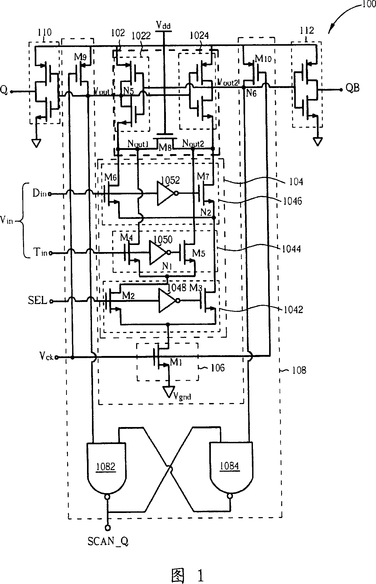
[0014] Please refer to FIG. 1 , which is a schematic diagram of an embodiment of a register circuit 100 of the present invention. The register circuit 100 includes: a latch circuit 102 , an input signal selection circuit 104 , a control circuit 106 and a scanning circuit 108 . The latch circuit 102 is used to latch an input data V in Generate an output data Q (please note that another output data QB is a complementary signal of the output data Q, so the output data Q or the output data QB can be selected according to the circuit design requirements). The input signal selection circuit 104 is respectively coupled to a non-test data D in with a test data T in , used to selectively output non-test data D in or test data T in to be processed by the register circuit 100 as the input data V in . The control circuit 106 is coupled to a drive clock V ck , used to drive the clock according to V ck Control whether the latch circuit 102 can latch the input data V in To determine...


PUM


Abstract

The present invention provides a register circuit, which includes a latch circuit for latching an input data and generating an output data; an input signal selecting circuit, which is coupled with a non-testing data and a testing date respectively, and is used to selectively output the non-testing data and the testing date to act as the input date; a control circuit, which is coupled on a drive clock, and is used to determine the output date according to that the drive clock controls whether the latch circuit can latch the input data; and a scan circuit, which is coupled on the drive clock and the latch circuit, and is used to generate a scan date according to the output date outputted by the drive clock scanning the latch circuit.

Description

technical field [0001] The invention relates to a circuit testing device and method, in particular to a register circuit applied to domino CMOS logic, a scan register circuit using the register circuit and a scanning method thereof. Background technique [0002] In order to improve the operation speed of the circuit, it has become the trend of today's digital logic circuits for designers to replace static circuits with dynamic circuits. Among them, dynamic circuits include domino CMOS conductor logic circuits, differential Dynamic cascade voltage swing logic circuit (Differential cascade voltage swing logic) and so on. Taking the domino CMOS logic circuit as an example, it uses a virtual N-type field-effect transistor (pseudo NMOS) architecture to implement its logic circuit. Compared with static circuits, this will greatly reduce the required power. The number of transistors, and the domino CMOS logic circuit has a small charge delay (pull-up delay) and a negligible short-...

Claims


Application Information

Patent Timeline
Patent Type & Authority Applications(China)
IPC IPC(8): G01R31/317G01R31/3185
Inventor 沈子宾谢尚志
Owner FARADAY TECH CORP
Why Eureka
Try Eureka