Drive device for pulsation type blood pump and its control method

A technology of driving device and control method, applied in medical science, prosthesis, etc., can solve the problem that the blood pump cannot become a system, etc.

Inactive Publication Date: 2008-03-26
SHANGHAI YIBISI ELECTRONICS TECH
View PDF0 Cites 10 Cited by
  • Summary
  • Abstract
  • Description
  • Claims
  • Application Information

AI Technical Summary

Problems solved by technology

It can be seen that these blood pumps cannot

Method used


Image

  • Drive device for pulsation type blood pump and its control method
  • Drive device for pulsation type blood pump and its control method
  • Drive device for pulsation type blood pump and its control method

Examples


Embodiment Construction

[0048]The embodiments of the present invention will be described in further detail below in conjunction with the accompanying drawings, but the present embodiments are not intended to limit the present invention, and any similar structures and similar changes of the present invention should be included in the protection scope of the present invention.

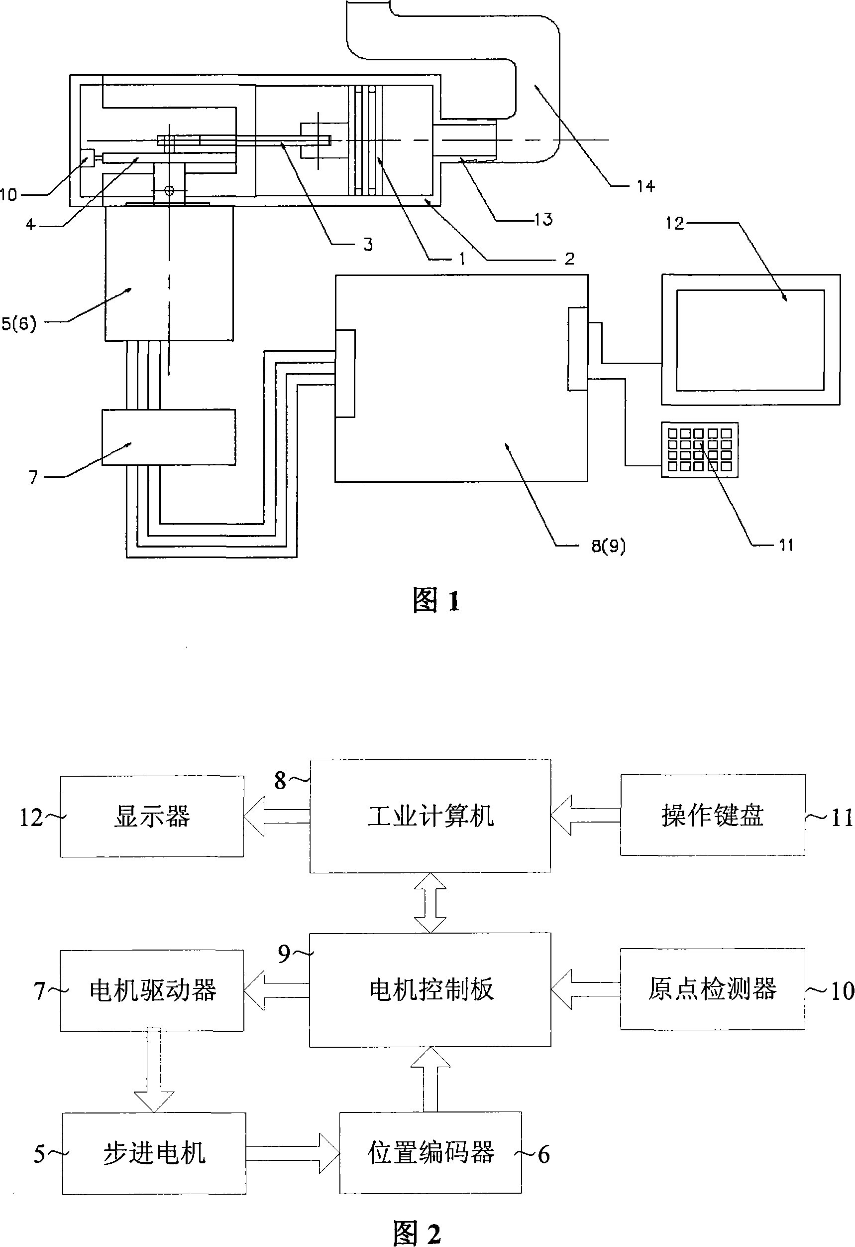
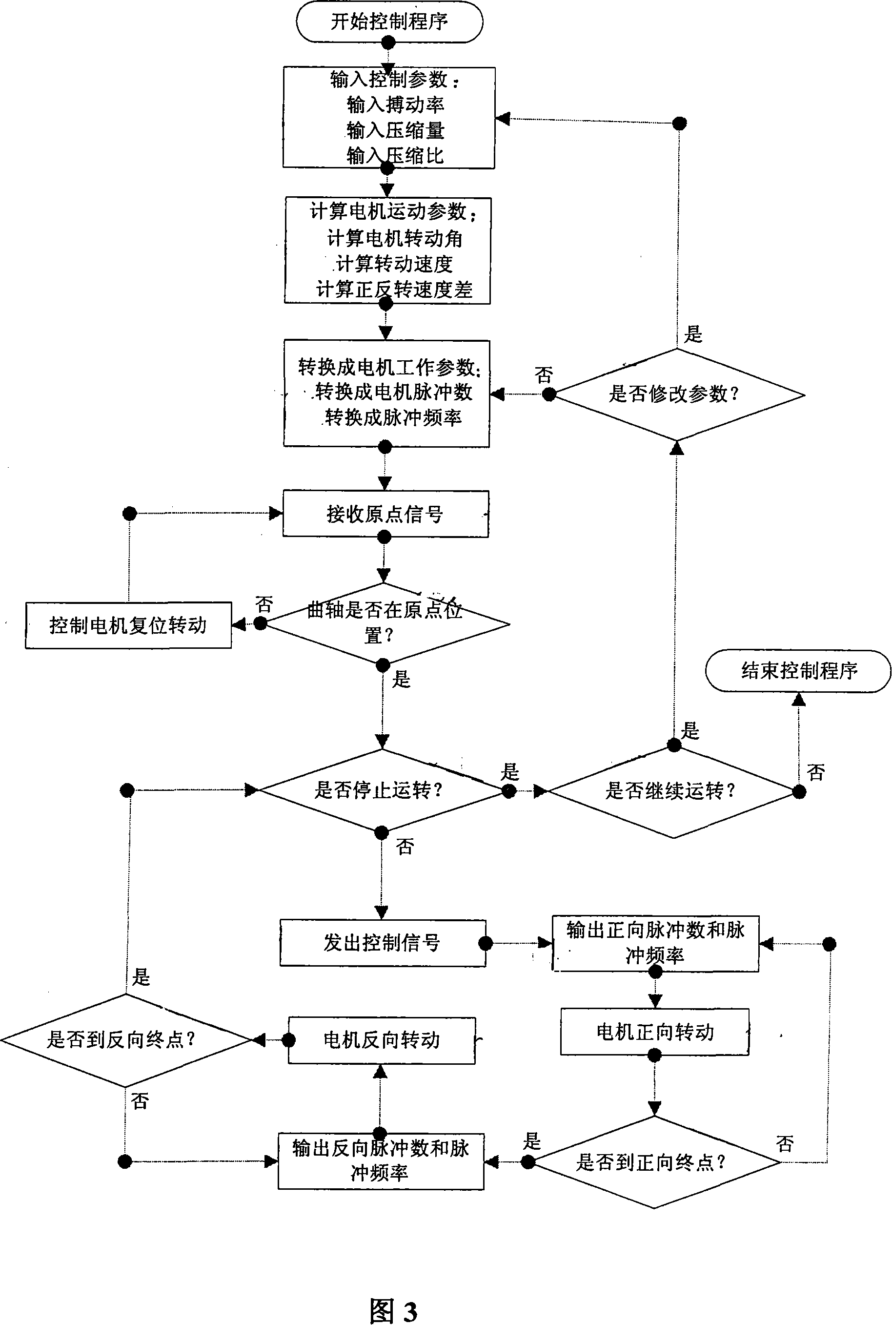
[0049] The embodiment of the present invention provides a driving device for a pulsatile blood pump and its control method. The technical solution adopted by the present invention to solve the above-mentioned problems is: a stepping motor is used to drive the crankshaft to push the piston, so that in the piston cavity Gas or liquid pressure is generated in the blood pump, and this pressure is sent to the air chamber (liquid chamber) of the blood pump through the pipeline. Positive pressure compresses the blood chamber, presses out blood, and generates compression pressure; negative pressure makes the blood chamber dilate, sucks ...


PUM


Abstract

The present invention relates to a drive device for pulsating type blood pump and its control method. Said drive device includes the following several portions: piston, piston cavity, connecting rod, crankshaft, stepping motor, motor driver, computer, initial point detector, operation keyboard, display, piston cavity nozzle and pressure pipeline. Said invention also provides its working principle and concrete operation method.

Description

technical field [0001] The invention relates to medical equipment technology, in particular to a driving device for a pneumatic or hydraulic pulsating blood pump and a control method thereof. Background technique [0002] Due to the development of various heart diseases, it gradually evolves into chronic congestive heart failure, and finally enters the end-stage of heart failure and dies due to decompensation. The main way to improve heart failure is to partially or completely replace the ventricle with a ventricular assist device (VAD) Blood pumping function, that is, artificial blood pump. At present, blood pumps commonly used in extracorporeal circulation in clinical cardiac surgery include pulsatile blood pumps and non-pulsatile blood pumps, namely advection blood pumps. In short-term application, the impact of pulsating blood flow and non-pulsating blood flow on the blood circulation of the body is not significant, but in long-term assistance, the effect of pulsating b...

Claims


Application Information

Patent Timeline
IPC IPC(8): A61M1/10A61M60/295A61M60/473A61M60/497
Inventor 潘钢陶勇冯明安
Owner SHANGHAI YIBISI ELECTRONICS TECH
Why Eureka
Try Eureka