Transfer loading device

A transfer device and transfer technology, applied in storage devices, transportation and packaging, claw arms, etc., can solve the problems of longer transfer distance and increased transfer weight, so as to reduce the movement load and shorten the action time Effect

Inactive Publication Date: 2008-03-26
MURATA MASCH LTD
View PDF1 Cites 9 Cited by
  • Summary
  • Abstract
  • Description
  • Claims
  • Application Information

AI Technical Summary

Problems solved by technology

[0008] However, in this transfer device 100, there is no problem when the workpiece W is small and light in weight,

Method used


Image

  • Transfer loading device
  • Transfer loading device
  • Transfer loading device

Examples


Example Embodiment

[0032] Hereinafter, embodiments (Examples) of the present invention will be described with reference to the drawings.
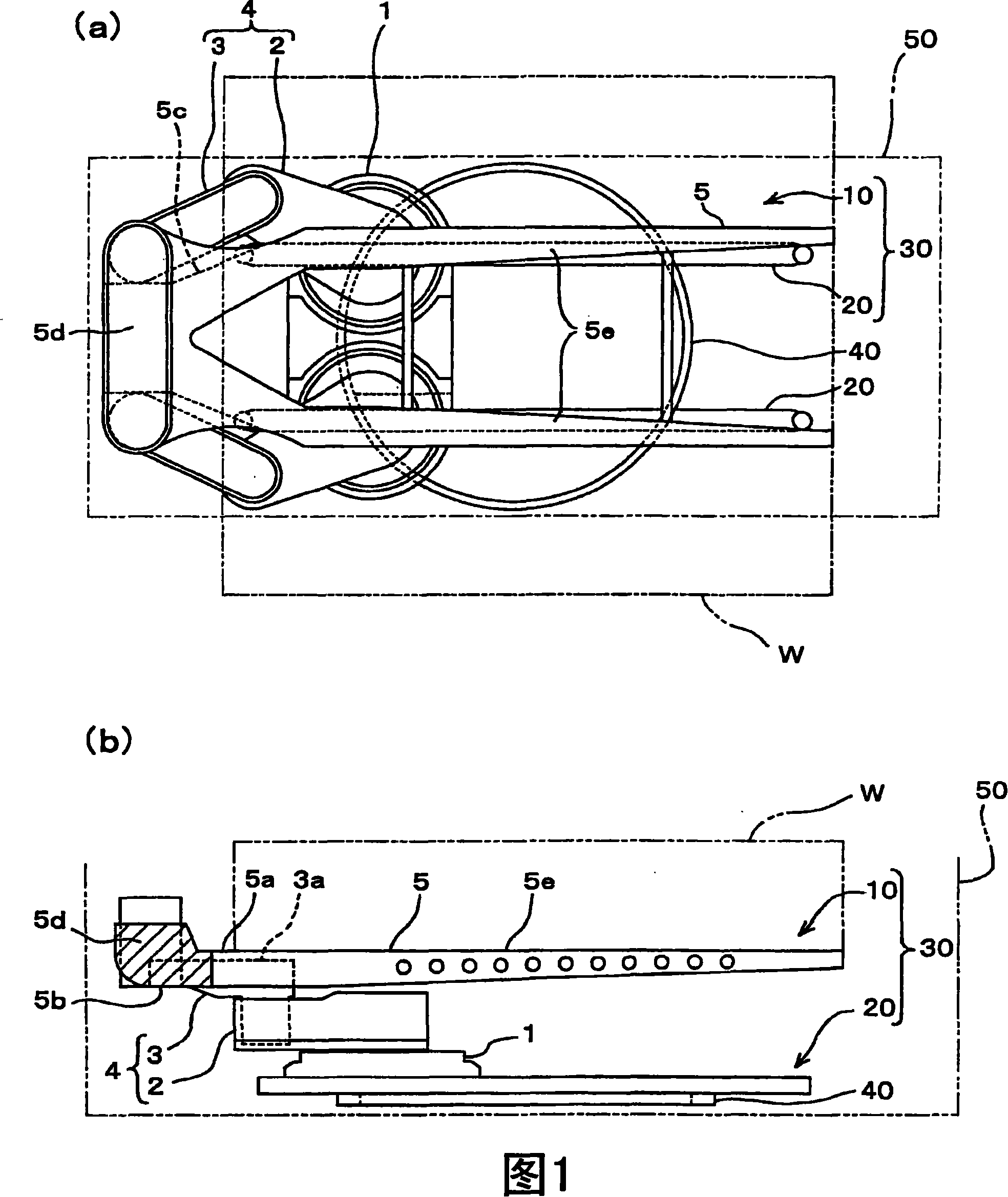
[0033] Fig. 1(a) is a front view showing an example of the transfer device of the present invention, and Fig. 1(b) is a side view of Fig. 1(a).

[0034] The transfer device 30 is a factory that manufactures, for example, semiconductor substrates, liquid crystal display panels, and the like, in order to perform various processing treatments on the flat blanks (semiconductor wafers or glass plates) in a clean room, each of which accommodates one sheet of the flat blanks. The blank pallet is a device used when the workpiece W, which is the object to be conveyed, is transferred in a state of being stacked in one or more stages.

[0035] Here, as an example of suitable use of the transfer device, the case where the tray containing the flat blanks is transported in the clean room is shown, but the transfer device of the present invention is not limited to this, and...


PUM


Abstract

A transfer loading device capable of transferring loading corresponding to large workpiece and avoiding particulate generating problem at the same time are provided in the present invention. A transfer loading device (30) installs base end sides of base end side arm (2) of a pair of free arms (4) composed of base end side arm (2) and front end side arm (3) separately on the base platform (1) running freely, having a transfer loading arm (5) leading the front end sides a pair of front end side arms (3) to run mutually and connect freely, having a sliding part (20) leading the base platform (1)to slide along transfer loading direction.

Description

technical field [0001] The present invention relates to a transfer device for linearly moving a workpiece in the same horizontal plane with a multi-joint arm, which is used in a conveyance system or the like for conveying a workpiece (referred to as "an object to be conveyed"). Background technique [0002] In a factory that manufactures semiconductor substrates or liquid crystal display panels, etc., multi-step processing is performed on different positions of the flat blank (semiconductor wafer or glass plate) as the blank, so it is necessary to have a storage space for storing the flat blank. A conveying system that conveys workpieces, such as pallets, within a clean room. In this conveyance system, a transfer device that linearly moves a workpiece in the same horizontal plane with a multi-joint arm is used. [0003] In this way, the use of multi-joint arm-type transfer devices (also known as "SCARA-type arms" (Selective Compliance Assembly Robot Arm with selective compl...

Claims


Application Information

Patent Timeline
IPC IPC(8): B65G47/74B65G35/00B65G1/04B65G49/06B65G49/07B25J18/00H01L21/677G02F1/1333
CPCB65G49/05H01L21/67706
Inventor 石川和广
Owner MURATA MASCH LTD
Why Eureka
Try Eureka