Drainage system estuary pier bar swirl chamber composite energy dissipation method

A drainage system and vortex chamber technology, applied in dams, coastline protection, dikes, etc., can solve problems such as uneven distribution of water flowing out of diffusion pools, increase drainage system investment, increase drainage pipe diameter, etc., and achieve obvious energy dissipation effect and design Simple, construction investment saving effect

Inactive Publication Date: 2008-03-26
CHINA INST OF WATER RESOURCES & HYDROPOWER RES
View PDF0 Cites 21 Cited by
  • Summary
  • Abstract
  • Description
  • Claims
  • Application Information

AI Technical Summary

Problems solved by technology

However, if too many stilling piers are arranged in the diffusion tank, the energy dissipation effect on the water flow may be increased, but the flow in the diffusion tank may affect the outflow capacity of the drainage pipe, which will inevitably require an increase in the diameter o...

Method used


Image

  • Drainage system estuary pier bar swirl chamber composite energy dissipation method
  • Drainage system estuary pier bar swirl chamber composite energy dissipation method
  • Drainage system estuary pier bar swirl chamber composite energy dissipation method

Examples


Embodiment 1

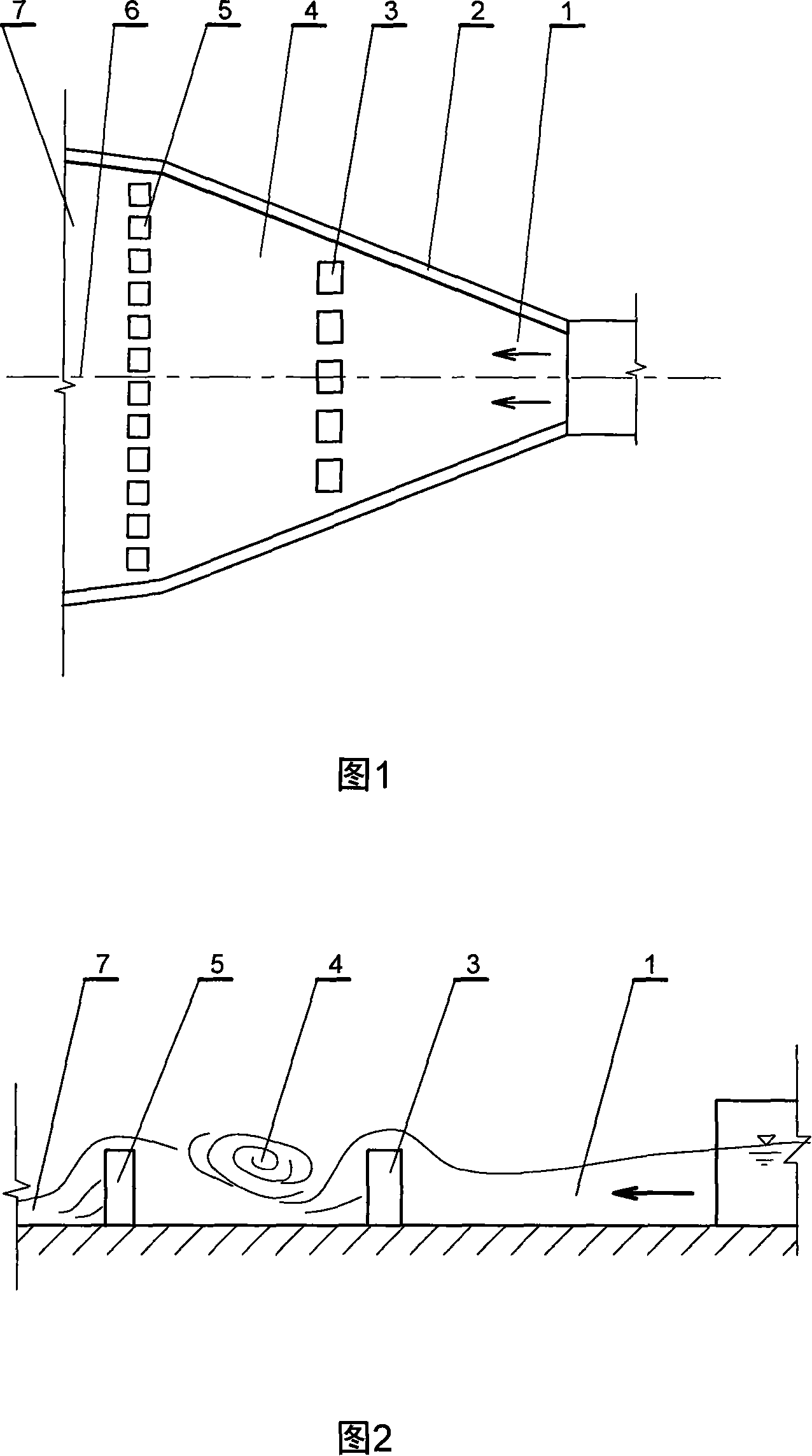
[0025] This embodiment is a composite energy dissipation method for the pier grid vortex chamber at the sea inlet of the drainage system, as shown in FIG. 1 . This example includes:

[0026] Water inlet 1: The water inlet can be connected with the outlet of the rainwater drainage culvert or the outlet of other hydraulic engineering.

[0027] Two opposite side walls 2 of the symmetrical diffusion pool: The symmetrical diffusion pool described in this embodiment is actually a pool composed of two opposite side walls. The plan view of this pool is an isosceles trapezoid formed by two symmetrical hypotenuse walls , the water inlet and the water outlet form the two bases of the isosceles trapezoid, the short side of the trapezoid is the water inlet, and the long side of the trapezoid is the water outlet, the concentrated outflow of water spreads out in the isosceles trapezoid, and diffuses from the water outlet out, so it is called symmetrical diffusion type. The function of symm...

Embodiment 2

[0084] This embodiment is a hydraulic energy dissipation facility for implementing the method described in Embodiment 1, as shown in FIG. 1 . Including the water inlet 1, two opposite side walls 2 of the symmetrical diffusion pool, and the water outlet 7, in the direction perpendicular to the central axis 6 of the diffusion pool between the two opposite side walls of the water inlet of the diffusion pool, and in a direction that can induce the incoming water flow to generate a strong water flow The first row of piers 3 composed of stilling piers is arranged at the jump position, and the second row of piers 5 composed of stilling piers is arranged at the outlet of the diffusion pool. The two rows of piers are arranged in parallel. A vortex chamber 4 capable of generating a strong vortex is formed between the second row of pier grids.

[0085] This embodiment is the basic shape of the pier-grid vortex chamber composite energy dissipation facility. The principle of this embodimen...

Embodiment 3

[0087] This embodiment is a preferred solution of Embodiment 2, as shown in FIG. 1 . The first row of pier grids in this embodiment is composed of a row of rectangular stilling piers, one side of the rectangular cross section of the rectangular stilling piers is perpendicular to the central axis of the symmetrical diffusion pool and is the edge facing the water.


PUM


Abstract

The present invention relates to hydraulic engineering, and is composite energy dissipating method with pier grating swirl chamber in the estuary of drainage system. The diffusion cell of the present invention includes a water inlet, side walls and a water outlet, and has one first row of pier grating comprising energy dissipating piers in the water inlet and one second parallel row of pier grating comprising energy dissipating piers in the water outlet to form one powerful swirl chamber in between. The present invention has obvious energy dissipating effect caused y hydraulic jump, swirl chamber and energy dissipating piers. The present invention has simple design, easy construction and low cost.

Description

technical field [0001] The invention relates to a compound energy dissipation method for a pier grid vortex chamber at a sea inlet of a drainage system, which is a water conservancy engineering method and facility for eliminating the water kinetic energy brought by a large amount of rainwater gushing out of the drainage outlet when the rainwater is discharged into the sea. Background technique [0002] In coastal cities, storm water generally flows into the sea through drainage systems. In places with huge rainfall, the water flow discharged at the outlet is very large. If no measures are taken at the outlet of the drainage pipe, it is very dangerous and will have a destructive impact on the surrounding ecological environment. For such a drainage system, it is very important to design hydraulic engineering facilities at the estuary with excellent hydraulic performance. The hydraulic engineering structure of the sea estuary should have sufficient energy dissipation capacity ...

Claims


Application Information

Patent Timeline
IPC IPC(8): E02B3/10
Inventor 杨开林董兴林王涛郭永鑫乔青松郭新蕾陈文学付辉崔巍
Owner CHINA INST OF WATER RESOURCES & HYDROPOWER RES
Why Eureka
Try Eureka