
Computer system electricity-saving state power management method

A computer system and power-saving state technology, which is applied in the direction of data processing power supply, etc., can solve problems such as no connection, insufficient battery power, and inability to switch power schemes in a timely manner, achieving the effect of small changes and low cost

Active Publication Date: 2008-03-26
LENOVO (BEIJING) CO LTD
View PDF0 Cites 12 Cited by
  • Summary
  • Abstract
  • Description
  • Claims
  • Application Information

AI Technical Summary

Problems solved by technology

[0006] The above-mentioned system has the following problems: the power supply scheme executed by the system is set according to the system state when entering S3. After entering S3, the system cannot know whether the AC power supply is plugged in or unplugged, or continue to execute according to the previously established scheme.
Specifically, when the AC power is turned on and there is no operation for 30 minutes, the system actively enters S3 and remains in the S3 state. If the AC power is unplugged during this period, the system will not know, so the system will not When it is woken up, it will not alarm until the battery power enters a low state (such as 10% or 3%), or wake up again and enter S4, causing the battery power to be seriously low when it is turned on again, affecting use
[0007] Therefore, the disadvantage of the existing power management scheme is that there is no connection between the provided AC scheme and the Cell scheme. After the system enters a power-saving state, it cannot obtain changes in external conditions (plugging and unplugging of the AC power supply), and cannot Timely switch power schemes

Method used


Image

  • Computer system electricity-saving state power management method
  • Computer system electricity-saving state power management method

Examples


Embodiment Construction

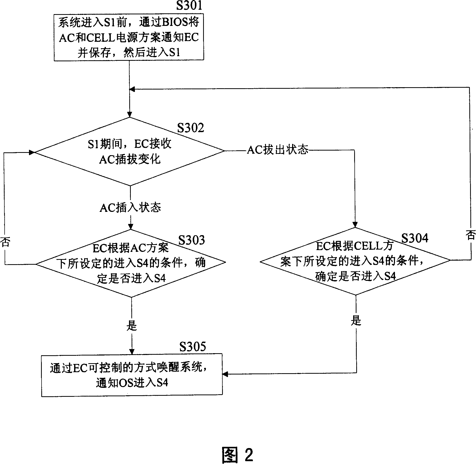
[0024] The present invention is not limited to the notebook computer, for the present invention, the necessary premise is that the system applying the present invention supports at least two different power-saving states (for example, S3 standby and S4 dormancy); moreover, the power management scheme also There are two different power management schemes (for example, AC scheme and CELL scheme) according to the plugging / unplugging status of the AC power supply. Therefore, those skilled in the art should understand that the following preferred embodiments are only exemplary descriptions of the present invention, and should not be construed as limiting the protection scope of the present invention.

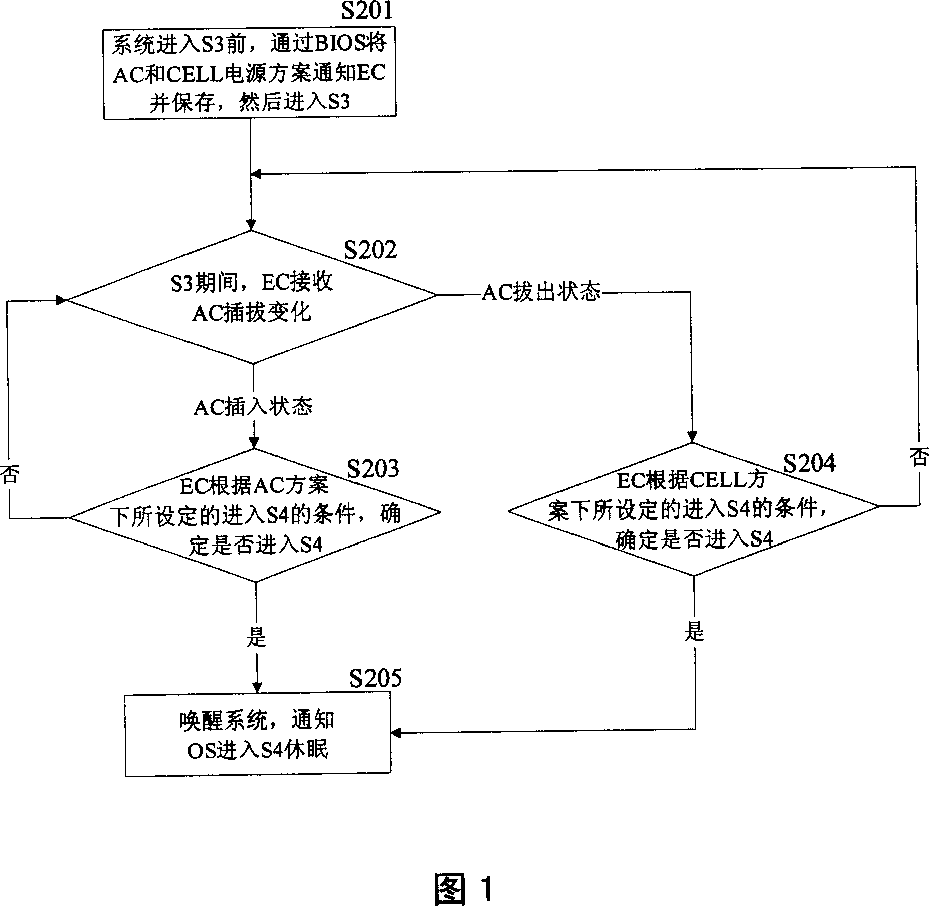
[0025] Hereinafter, taking a notebook computer, S3 standby and S4 hibernation, and the AC scheme and the CELL scheme as examples, referring to FIG. 1 , the preferred embodiment of the present invention will be described in detail.

[0026] In step S201, before the system enters S3, t...


PUM


Abstract

This invention offers a kind of power pack management method in the state of battery-conserving for the computer system which concludes the follow steps: before the computer system inters the first battery-conserving state it makes the first and second power pack management methods informed the embedded controller and holds it in the memorizer which can be called on by the embedded controller and then the computer system inters the first battery-conserving state; during the first battery-conserving state the embedded controller detects the AC power pack connection state in timing and periodicity; if detected the AC power pack were in the insert state the embedded controller can determine whether inter the battery-conserving state or not according to condition of interring the second battery-conserving state set by the first power pack management method; if detected the AC power pack were in the pull state the embedded controller can determine whether inter the battery-conserving state or not according to condition of interring the second battery-conserving state set by the second power pack management method; when it determines to inter the second saving state the embedded controller rouses the computer system and informs the computer system inter the second battery-conserving state.

Description

technical field [0001] The present invention relates to a computer system power supply management scheme, more specifically, to a power supply management method in a computer system power saving state. Background technique [0002] Existing notebook computers generally have at least two power sources: external power source (AC power source) / internal power source (battery power source). According to the ACPI (Advanced Configuration and Power Interface) power management specification, the power management of the computer has six states, namely S0, S1, S2, S3, S4 and S5. Among them, S0 is the normal working state of the system and consumes a lot of power; S5 It is the state that the computer is turned off. At this time, the power of the computer is turned off and the power consumption is zero. Usually, after the computer exits the operating system (except for a complete shutdown), the notebook can also enter different levels of power-saving modes S1, S2, S3, and S4, among whic...

Claims


Application Information

Patent Timeline
IPC IPC(8): G06F1/32
Inventor 李众庆景涛
Owner LENOVO (BEIJING) CO LTD
Learn More