Liquid crystal display panel and its driving circuit

A technology of liquid crystal display panel and driving circuit, applied in static indicators, instruments, etc., can solve the problem of display panel screen flicker and other problems, and achieve the effect of overcoming screen flicker

Inactive Publication Date: 2008-03-26
INNOCOM TECH SHENZHEN +1
View PDF0 Cites 9 Cited by
  • Summary
  • Abstract
  • Description
  • Claims
  • Application Information

AI Technical Summary

Problems solved by technology

[0008] In order to solve the problem of flickering of the LCD panel screen driven by the LCD panel driving circuit in the prior art, it is necessary to provide a liquid crystal display panel driving circuit that can effectively overcome the screen flickering

Method used


Image

  • Liquid crystal display panel and its driving circuit
  • Liquid crystal display panel and its driving circuit
  • Liquid crystal display panel and its driving circuit

Examples


Embodiment Construction

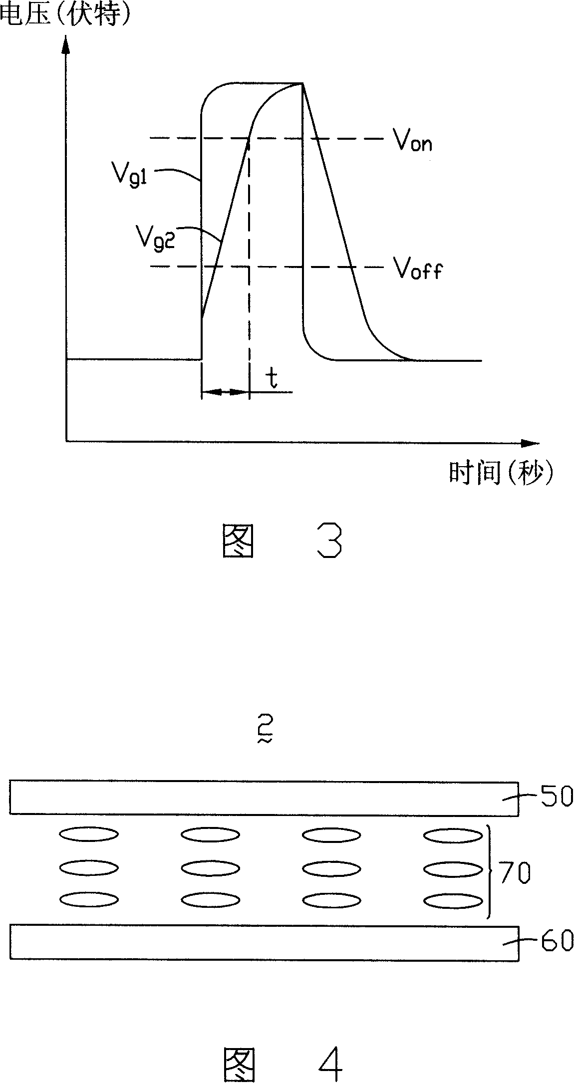
[0019] Please refer to FIG. 4 , which is a schematic structural diagram of a liquid crystal display panel of the present invention. The liquid crystal display panel 2 includes a first substrate 50 , a second substrate 60 and a liquid crystal layer 70 between the two substrates 50 , 60 . The liquid crystal display panel 2 is driven by a driving circuit (not shown).

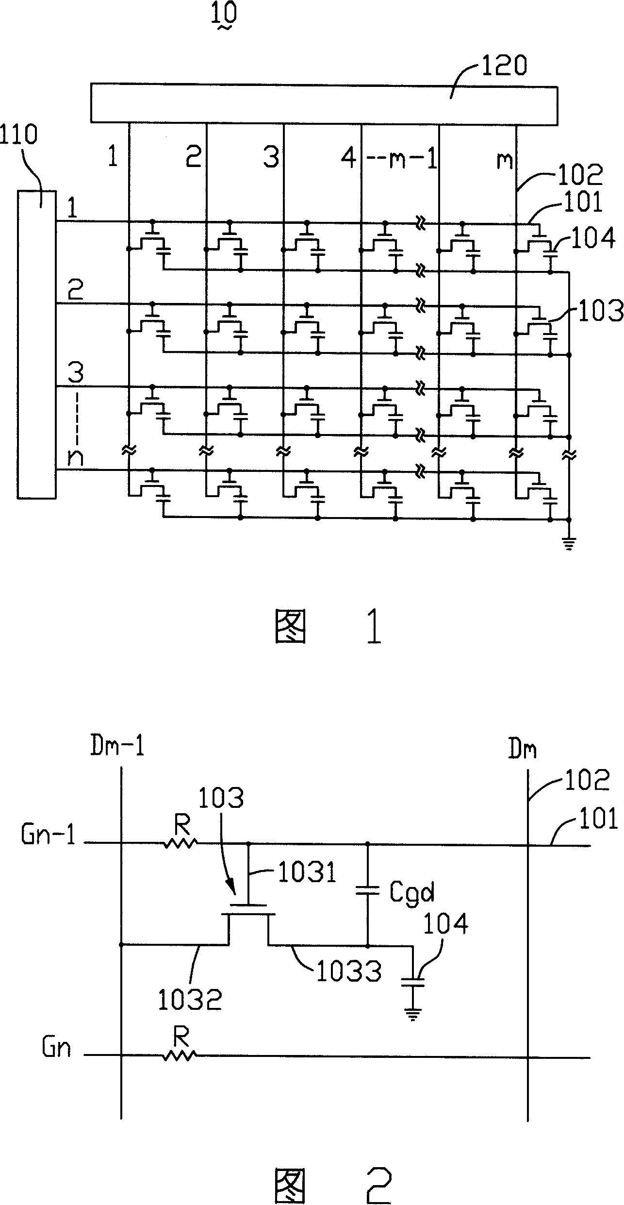
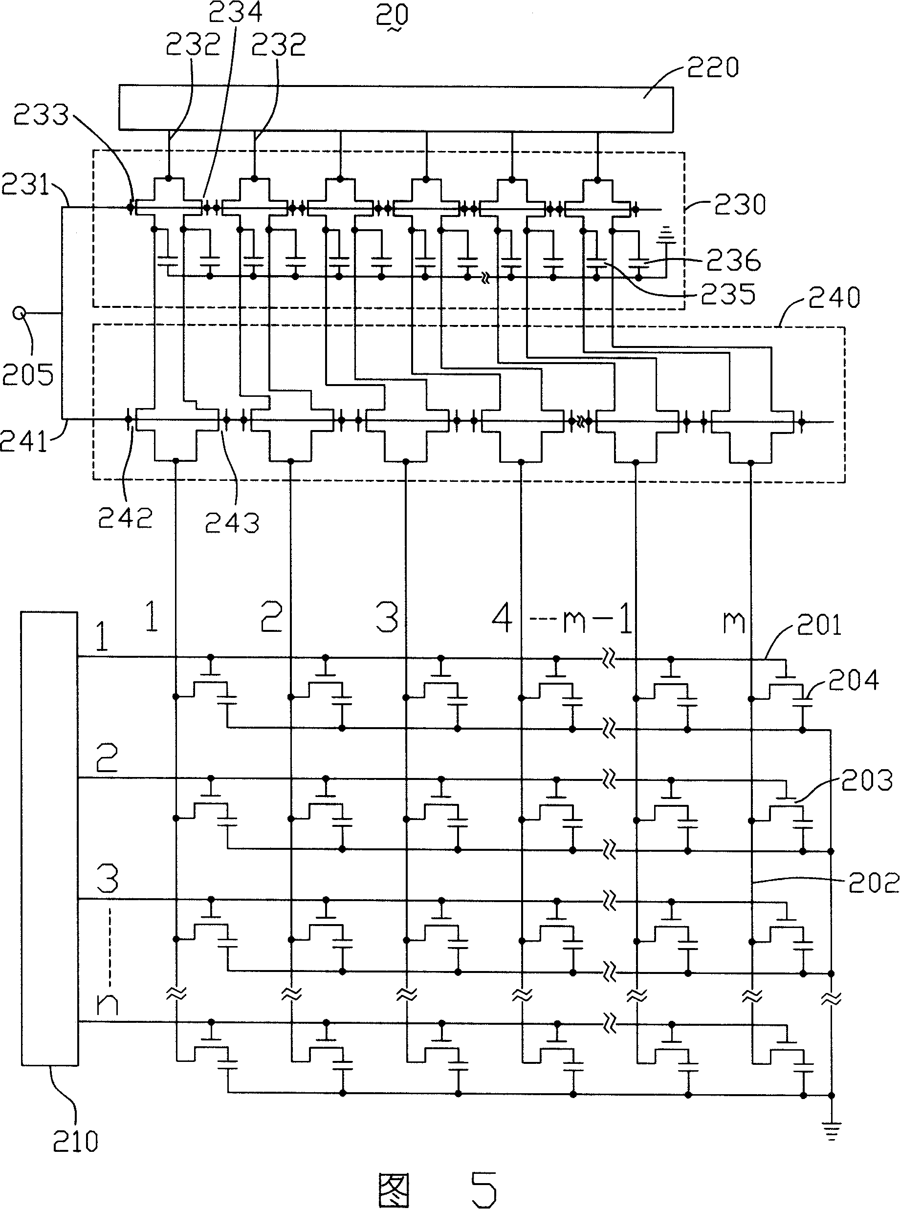
[0020] Please refer to FIG. 5 , which is a schematic diagram of a preferred embodiment of the driving circuit of the liquid crystal display panel 2 . The driving circuit 20 includes a scanning driving circuit 210, a data driving circuit 220, an access unit 230, an output control unit 240, a signal input terminal 205, a plurality of scanning lines 201 parallel to each other, and a plurality of parallel scanning lines 201 parallel to each other. The scan line 201 vertically insulates and crosses the first data line 202 , a plurality of thin film transistors 203 and a plurality of pixel electrodes 204 located at inte...


PUM


Abstract

The liquid crystal display- panel drive circuit comprises a plurality of scanning lines, a plurality of first data lines insulated intersecting the scanning lines, a plurality of film transistors at the cross point of the scanning lines and the first data lines, a scanning drive circuit, a data drive circuit, an access unit and an output control unit. The scanning drive circuit is used for producing a plurality of scanning signals. The data drive circuit is used for producing a plurality of data signals. The access unit is used for accessing multiple signals output by the data drive circuit. The output control unit is used for receiving the data signals accessed by the access unit and controlling the time for outputting the data signals to the first data lines to make the time in accordance with turn-on time of multiple film transistors.

Description

technical field [0001] The invention relates to a liquid crystal display panel and a driving circuit thereof. Background technique [0002] Liquid crystal display panels have been widely used in electronic display devices such as televisions and notebook computers due to their low radiation and thin thickness. Usually, the liquid crystal display panel needs a driving circuit to drive it. As the size of the liquid crystal display panel increases, the length of the scanning lines of its driving circuit also increases accordingly. However, the increase in the length of the scanning line will increase the delay of the scanning signal, which will cause the flickering problem of the LCD panel. [0003] Please refer to FIG. 1 , which is a schematic diagram of a driving circuit of a liquid crystal display panel in the prior art. The driving circuit 10 includes a plurality of scanning lines 101 parallel to each other, a plurality of data lines 102 parallel to each other and perpen...

Claims


Application Information

Patent Timeline
Patent Type & Authority Applications(China)
IPC IPC(8): G09G3/36G09G3/20G02F1/133
Inventor 孟锴祁小敬
Owner INNOCOM TECH SHENZHEN
Why Eureka
Try Eureka