This helps you quickly interpret patents by identifying the three key elements:
Problems solved by technology
Method used
Benefits of technology
Problems solved by technology
If the uniformity of illuminance is poor, there will be a problem that uniform treatment cannot be performed across the entire light irradiation area.
Method used
Image
Click on the blue label to locate the original text in one second.
Reading with bidirectional positioning of images and text.
Examples
experiment example
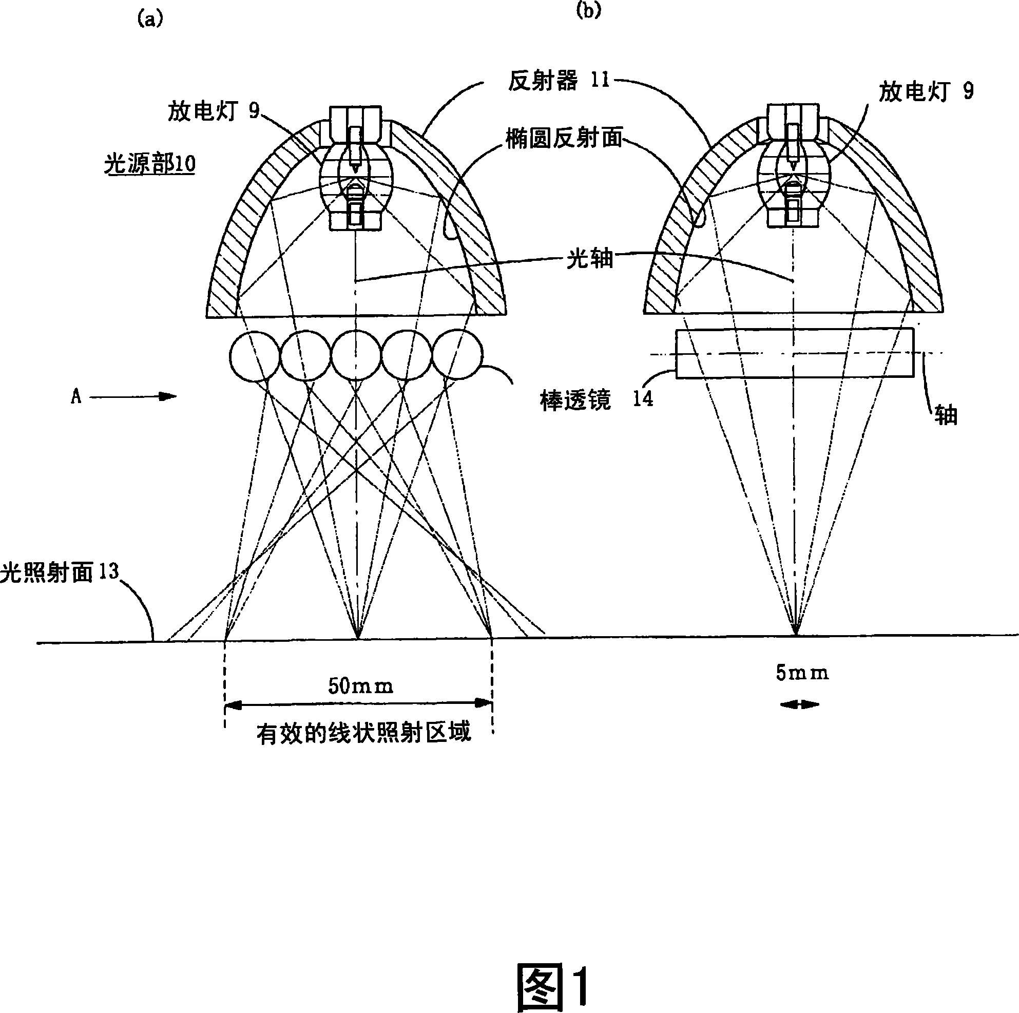
[0121] Using the light irradiator of the first embodiment shown in FIG. 1 , the number of rod lenses was changed, and the illuminance distribution of the light irradiation area on the light irradiation surface W where light was collected linearly was measured.
[0122] Fig. 4 shows the results. The coaxial vertical axis is the integrated light quantity (relative value), and the horizontal axis is the irradiation width (length) (mm).
[0123] Each curve in Fig. 4 represents the number of rod lenses arranged on the light exit side of the reflector respectively, for (A) no rod lens, (B) 1 rod lens, (C) 2 rod lenses, (D) Seven rod lens cases.
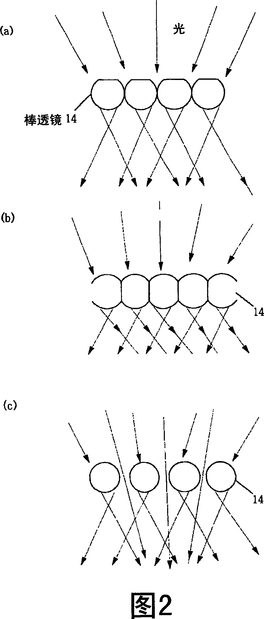
[0124] Furthermore, as shown in FIG. 5, the rod lens 14 provided on the light emitting side of the reflector 11 changes the size so that the light reflected by the reflector can enter the rod lens.
[0125] That is, when there is one rod lens, the diameter R of the rod lens is made equal to or slightly larger than the diameter of the opti...
no. 2 Embodiment
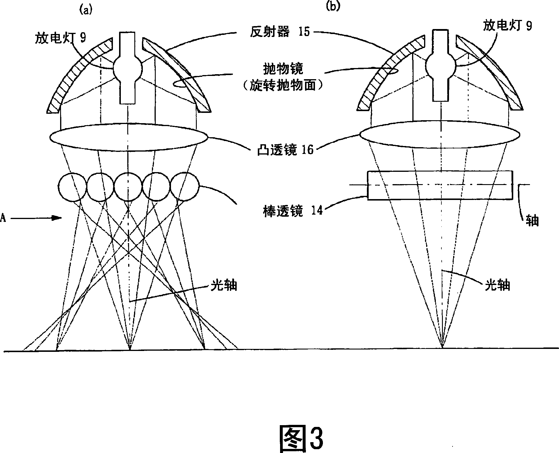
[0131] Fig. 6 is a diagram showing a second embodiment of the present invention configured to obtain a longer linear light irradiation area. 6 shows a light irradiator capable of obtaining a long-line light irradiation region using two sets of light source units 10 shown in FIG. 1 , but two sets of light irradiators shown in FIG. 3 above may be used.
[0132] In FIG. 6, the light source parts 101 and 102 have the same structure as the light source part 10 shown in FIG. The spheroidal reflective surface centered on its optical axis, the light-emitting part of the discharge lamp 9 (for example, the bright spot of the arc), is located at the first focal point of the reflector 11 having the spheroidal reflective surface.
[0133] In each light source unit 101, 102, the light from the discharge lamp 9 is reflected by the reflector 11, and enters the rod lens 14. A linear spotlight extending in a direction.
[0134] In the embodiment shown in FIG. 6 , each light source unit 101, 1...
PUM
Abstract
A light irradiation device that is capable of good irradiance uniformity in the lengthwise direction and that is applicable to an inkjet printer. A light-emitting portion of a short-arc type discharge lamp is positioned at the first focal point of a reflector that has a reflecting surface in the shape of an ellipsoid of revolution, and the light from the discharge lamp is reflected by the reflector and is focused at the second focal point; after which the light is incident on multiple, columnar rod lenses 14 . Of the light that is incident on the rod lenses, the light along the axial direction is focused at the second focal point of an elliptical reflector without being affected by the rod lenses, and the light along the direction perpendicular to the axial direction is focused by the rod lenses and then spreads and irradiates the light irradiation surface.
Description
technical field [0001] The present invention relates to a light irradiator and an inkjet printer for forming a linear elongated light irradiation region using a short arc lamp, and more particularly to a method for irradiating light by forming a linear light irradiation region whose illuminance distribution is uniform on an object to be irradiated with light A light irradiator, and an inkjet printer equipped with the light irradiator, which discharges a photocurable liquid material onto a base material and records patterns such as images or circuits on the base material. Background technique [0002] Since images can be easily and inexpensively produced by the gravure printing method, in recent years, the inkjet recording method has been used in various printing fields such as photography, various printing, marking, and special printing of color filters. . [0003] Especially in the inkjet recording method, high image quality can be obtained by combining an inkjet printer, ...
Claims
Application Information
Patent Timeline
Application Date:The date an application was filed.
Publication Date:The date a patent or application was officially published.
First Publication Date:The earliest publication date of a patent with the same application number.
Issue Date:Publication date of the patent grant document.
PCT Entry Date:The Entry date of PCT National Phase.
Estimated Expiry Date:The statutory expiry date of a patent right according to the Patent Law, and it is the longest term of protection that the patent right can achieve without the termination of the patent right due to other reasons(Term extension factor has been taken into account ).
Invalid Date:Actual expiry date is based on effective date or publication date of legal transaction data of invalid patent.

