Method and construction for preventing water leakage in diaphragm type compression pump

A pressure pump and diaphragm technology, applied in the field of pressure pumps, can solve the problems of diaphragm pressure pump damage, reduced boosting efficiency, pressure loss and so on.

Active Publication Date: 2008-04-02
蔡应麟 +1
View PDF16 Cites 25 Cited by
  • Summary
  • Abstract
  • Description
  • Claims
  • Application Information

AI Technical Summary

Problems solved by technology

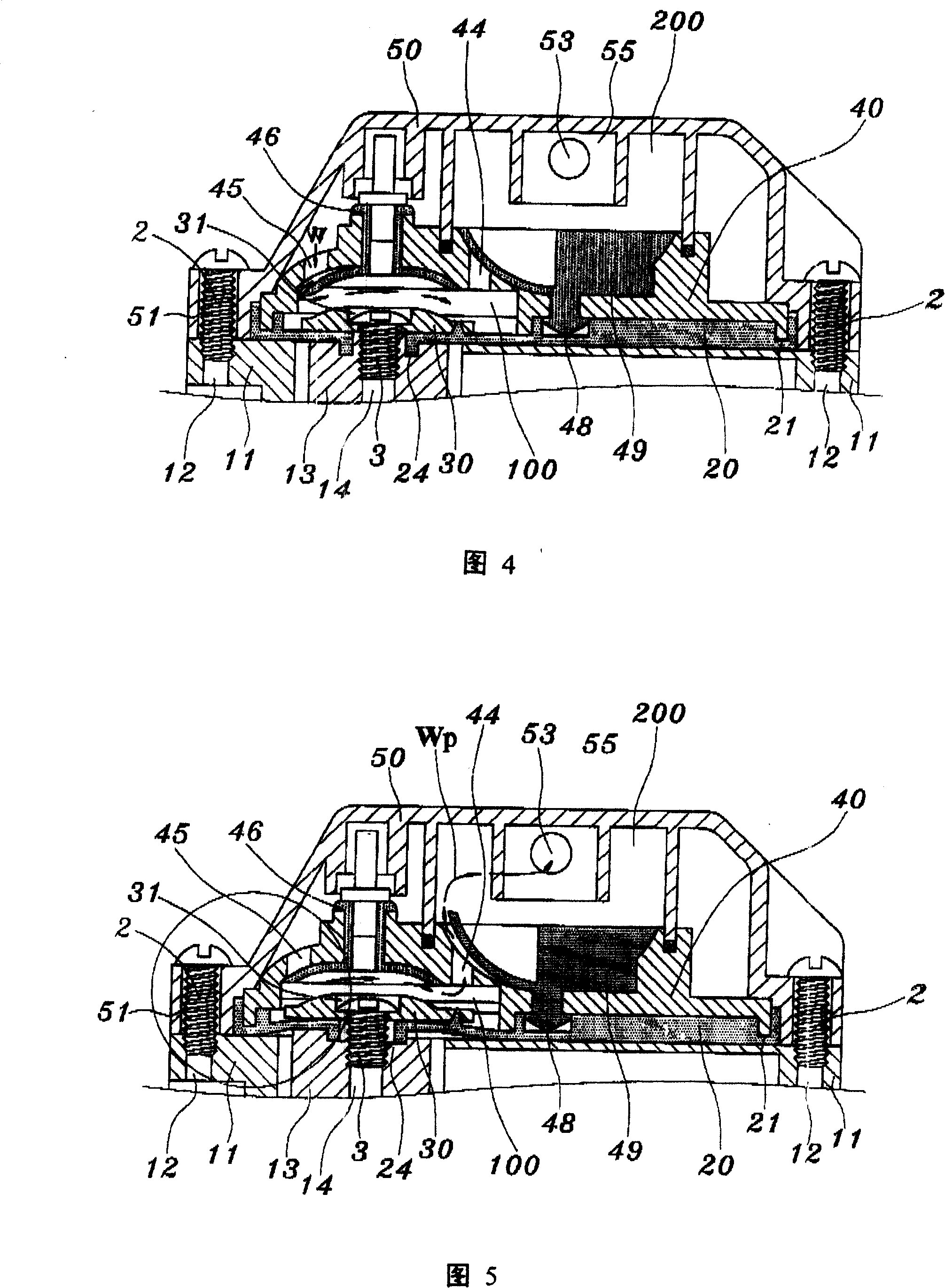
[0007] All the conventional diaphragm pressure pumps disclosed above have a serious defect. As shown in Figures 6 to 9, when the motor 10 is started to pressurize, the balance wheels 13 are in contact with the diaphragm. Therefore, when the balance wheel 13 swings and pushes forward each time, and the piston actuating area 23 of the diaphragm 20 moves, the diaphragm clamped between the piston push block 30 and the balance wheel 13 The 20 position will be stretched once (as shown by the imaginary line in Figure 8), if the rotating speed of the motor 10 is 700 revolutions per minute (700rpm), then the diaphragm 20 position will be stretched 700 times per minute, After such a high-frequency stretching action and use for a period of time, the diaphragm 20 at the piston action area 23 will gradually form an incomplete airtight seal with the bottom surface of the piston push block 30 due to the pull. As a result (as shown in FIG. 9 ), the high-pressure water Wp leaks into the output shaft of the motor 10 through the space between the fixing screw 3 and the threaded hole 14 of the balance wheel 13 , and finally causes a short circuit in the electrical circuit of the motor 10 . The entire diaphragm pressure pump is damaged and cannot be used. This major problem has not yet been solved in the manufacturing industry. Consumers can only gamble and spend the same price but n

Method used


Image

  • Method and construction for preventing water leakage in diaphragm type compression pump
  • Method and construction for preventing water leakage in diaphragm type compression pump
  • Method and construction for preventing water leakage in diaphragm type compression pump

Examples


Embodiment Construction

[0061] As shown in Fig. 11 to Fig. 13, the method and structure thereof for preventing water leakage in a diaphragm type pressure pump of the present invention is to first set a screw hole on the top surface of each piston actuation area 63 of the diaphragm 60. A hollow cylinder 64 is formed, and the hollow cylinder 64 and the diaphragm 60 are integrally injection-molded with plastic material having the same elasticity (as shown in view A in FIG. 11 and FIG. 12 ), and its outer diameter is equal to or slightly smaller than The inner diameter of the stepped hole 31 in the piston push block 30, and then the stepped hole 31 of the piston push block 30 is placed on the outer edge of the hollow cylinder 64 (as shown in the view of B in Figure 12), and then threaded through the set screw 3 pass through the central hole of the hollow cylinder 64 (as shown in the view of C in FIG. 12 ), and apply force to lock the fixing screw 3 into the threaded hole 14 of the balance wheel 13. During...


PUM


Abstract

The invention relates to a preventing leakage water method and structure of diaphragm type pressure pump, wherein, hollow cylinders are respectively arranged on the acting zone of each piston relative to the screw holes of each balance wheel in the diaphragm sheet of the diaphragm type pressure ump. Every hollow cylinder is covered in a ladder hole of every piston pushing lump and passes through the central hole of the hollow cylinder by a fixing screw. During the screwing and fixing the screw hole of every swing wheel, the travel synchronous presses through the upper section of the hollow cylinder to expand and deform toward surroundings gradually. An interdiction structure of stopping water pressure leakage is formed between the bottom of the fixing screw head and the ladder hole top face of the piston pushing lump, thereby further preventing water pressure leakage and electrical short circuit and damage of pressure pump further after following into motor.

Description

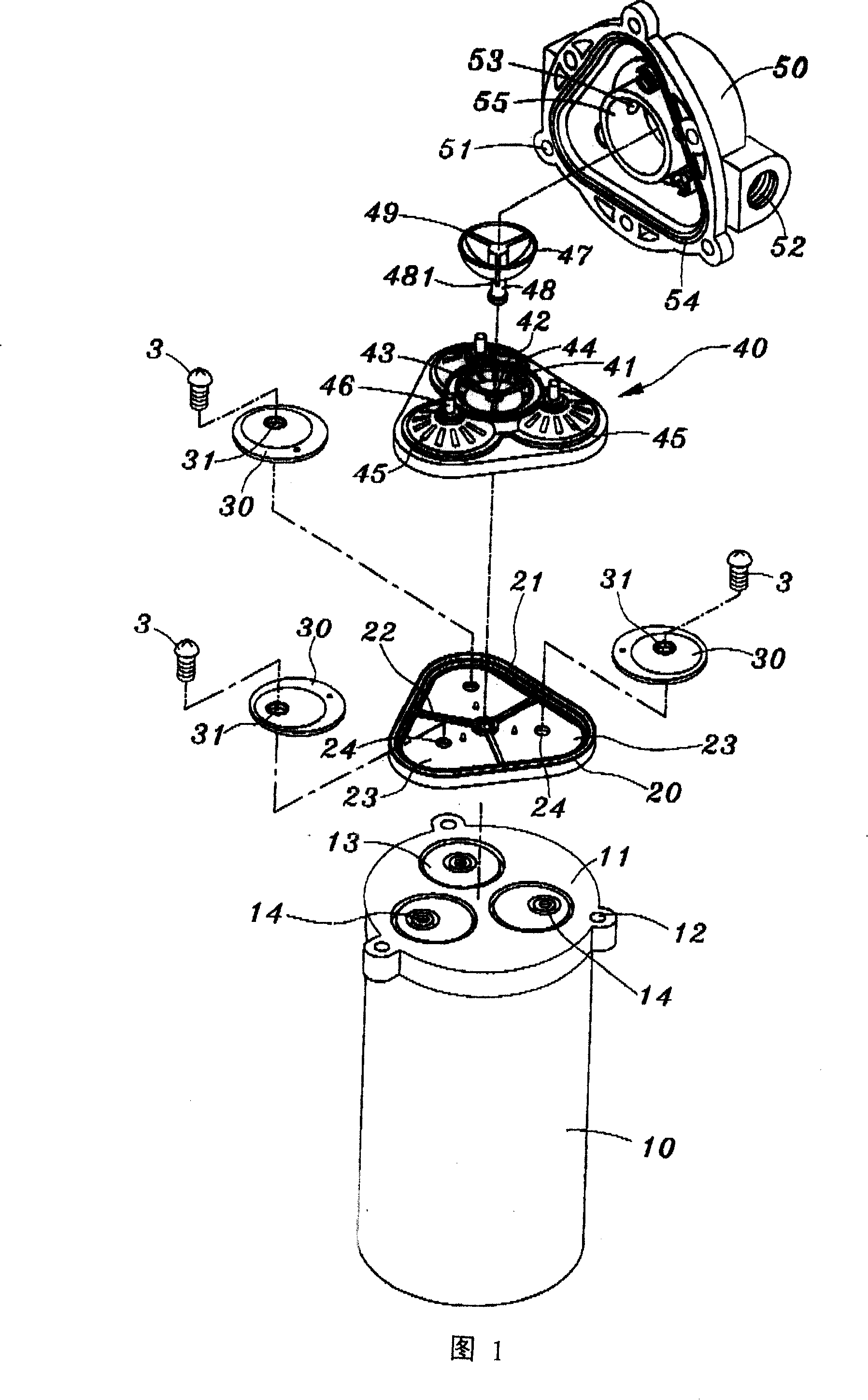
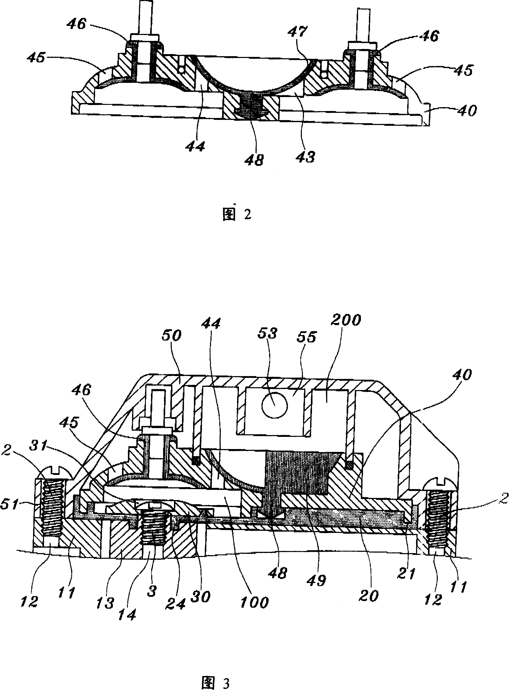
technical field [0001] The present invention relates to a special pressure diaphragm pump for reverse osmosis water filter (reverse osmosis purification), in particular to a pressure diaphragm pump that can prevent the water pressure inside the pump body from leaking into the motor, so as to completely solve the problems caused by water seepage in existing pressure pumps. The lack of damage caused by electrical short circuit due to leakage belongs to the field of pressure pumps. Background technique [0002] Diaphragm pressure pumps for reverse osmosis water filters are currently known, such as US patents 4396357, 4610605, 5476367, 5571000, 5615597, 5626464, 5649812, 5706715, 5791882, 5816133, 6048183, 6089838, 629941 No. 6604909, 6840745 and 6892624 etc. are all, and its structure as shown in Fig. 1 to Fig. 3, is to comprise: a motor 10; One is positioned at this motor 10 output shafts (not shown on the figure) top cover seat 11, A plurality of screw holes 12 are set on th...

Claims


Application Information

Patent Timeline
IPC IPC(8): F04B43/04
Inventor 徐兆火
Owner 蔡应麟
Why Eureka
Try Eureka