Ethernet self-adaption method, device and system based on FPGA

An Ethernet and adaptive technology, applied in transmission systems, digital transmission systems, network interconnection, etc., can solve the problems of weak stability, poor adaptability, and inflexibility of using dedicated interfaces for three-speed Ethernet adaptive technology, and achieve Improve application applicability, easy application and strong portability

Pending Publication Date: 2020-05-08
博依特(广州)工业互联网有限公司
View PDF9 Cites 2 Cited by
  • Summary
  • Abstract
  • Description
  • Claims
  • Application Information

AI Technical Summary

Problems solved by technology

[0003] In the prior art, it has been possible to add the function of Ethernet self-adaptation in the PHY chip, but since most of the existing Ethernet self-adaptive technologies are realized by using software and dedicated interfaces, the three-speed Ethernet self-adaptive technology has been brought Weak stability, inflexibility and poor adaptability when using dedicated interfaces

Method used


Image

  • Ethernet self-adaption method, device and system based on FPGA
  • Ethernet self-adaption method, device and system based on FPGA
  • Ethernet self-adaption method, device and system based on FPGA

Examples


Embodiment 1

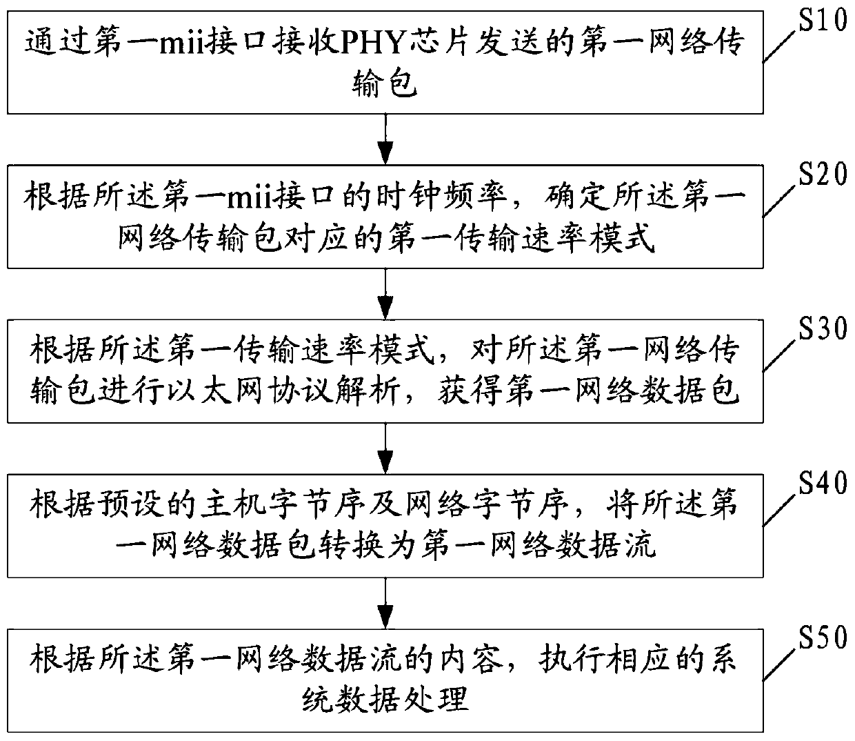
[0042] figure 1 Shown is a schematic flowchart of the FPGA-based Ethernet self-adaptation method according to Embodiment 1 of the present invention.

[0043] Such as figure 1 As shown, the method includes the following steps:

[0044] S10: Receive the first network transmission packet sent by the PHY chip through the first mii interface;

[0045] S20: Determine the first transmission rate mode corresponding to the first network transmission packet according to the clock frequency of the first mii interface;

[0046] Specifically, the 10M broadband Ethernet transmission mii interface clock is 2.5M, each clock transmits 4bit data, two clocks transmit 8bit data, that is, 1byte data; the 100M broadband Ethernet transmission mii interface clock is 25M, each clock 4bit data is transmitted, two clocks transmit 8bit data, that is, 1byte data; 1000M broadband Ethernet transmission mii interface clock is 125M, each clock transmits 8bit data, and the rising edge and falling edge of th...

Embodiment 2

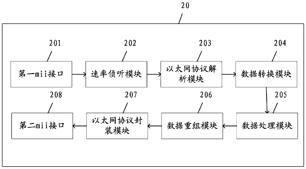
[0062] figure 2 Shown is a schematic structural diagram of an FPGA-based Ethernet adaptive device according to Embodiment 2 of the present invention.

[0063] Such as figure 2 As shown, the device includes: a first mii interface, a rate monitoring module, an Ethernet protocol analysis module, a data conversion module and a data processing module, wherein,

[0064] The first mii interface is used to receive the first network transmission packet sent by the PHY chip;

[0065] Wherein, the first mii interface can be any one of rgmii interface, rmii interface, smii interface, ssmii interface, gmii interface or sgmii interface. Compared with the data transmission interface in the prior art, the inherent function chip has been defined. Dedicated interface, the data transmission interface in Embodiment 2 of the present invention is more flexible in selection.

[0066] The rate listening module is used to determine the first transmission rate mode corresponding to the first netwo...

Embodiment 3

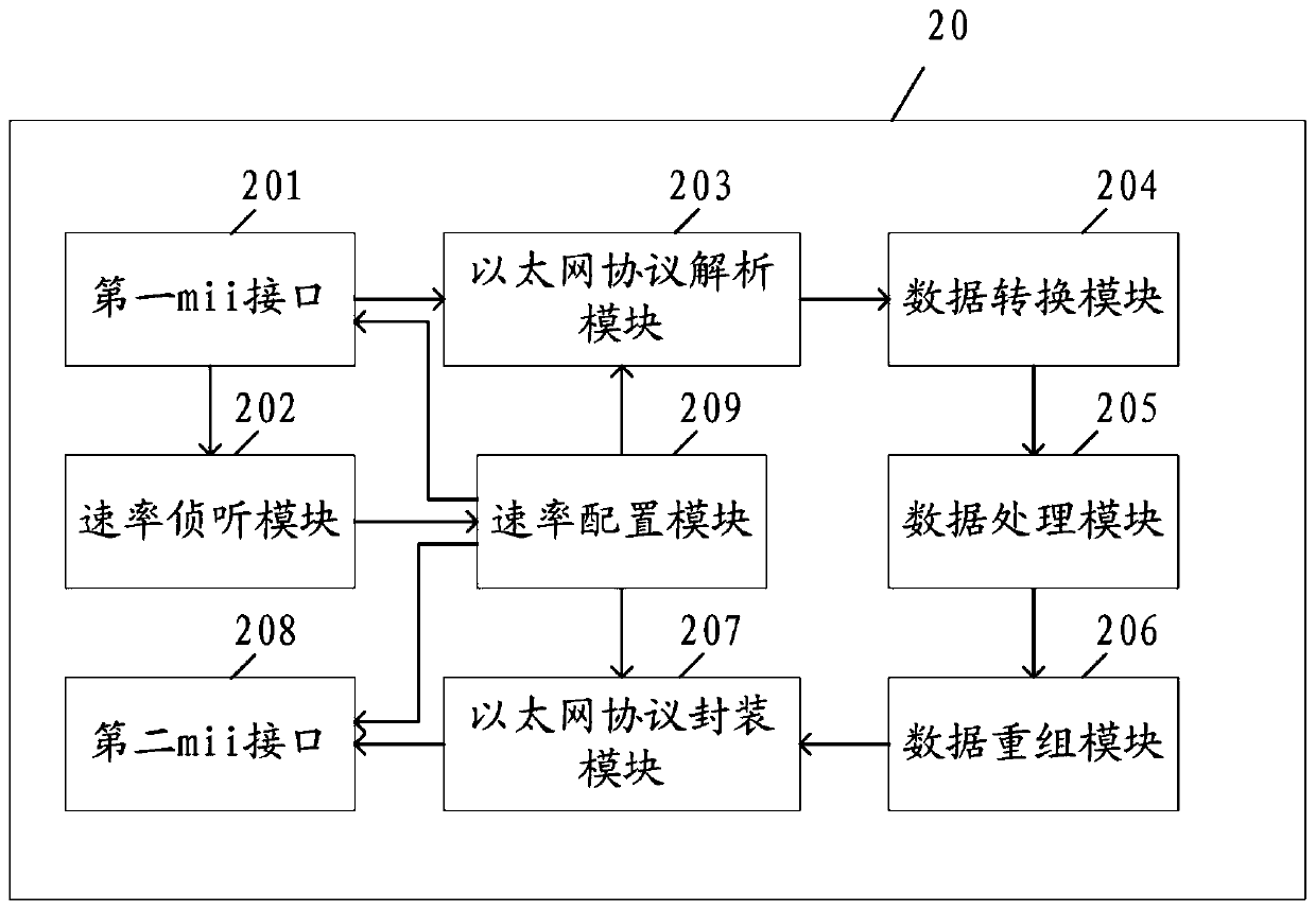
[0083] image 3 Shown is a schematic structural diagram of an FPGA-based Ethernet adaptive device according to Embodiment 3 of the present invention.

[0084] Preferably, the FPGA-based Ethernet adaptive device of embodiment three, on the basis of embodiment two, also includes a rate configuration module, and its structural diagram is as follows image 3 shown;

[0085] Its workflow is basically the same as that of Embodiment 2, and details will not be repeated here. The difference is that: after the rate monitoring module determines the first transmission rate mode corresponding to the first network transmission packet, the first transmission rate is set by the rate configuration module. The mode is configured to the first mii interface, the Ethernet protocol analysis module, the Ethernet protocol encapsulation module and the second mii interface, the first mii interface, the Ethernet protocol analysis module, the Ethernet protocol encapsulation module and the second mii int...


PUM


Abstract

The invention relates to the technical field of Ethernet self-adaption, and discloses an Ethernet self-adaption method, device and system based on an FPGA, and the method comprises the steps: receiving a first network transmission package transmitted by a PHY chip through a first mii interface; determining a first transmission rate mode corresponding to the first network transmission packet according to the clock frequency of the first mii interface; performing Ethernet protocol analysis on the first network transmission packet according to the first transmission rate mode to obtain a first network data packet; converting the first network data packet into a first network data stream according to a preset host byte sequence and a preset network byte sequence; and executing corresponding system data processing according to the content of the first network data stream. According to the Ethernet self-adaption method, device and system based on the FPGA, the stability of Ethernet self-adaption is enhanced through a hardware architecture, interfaces can be flexibly selected through a programmable configuration interface, and the application adaptability of the interfaces is improved.

Description

technical field [0001] The invention relates to the technical field of Ethernet self-adaptation, in particular to an FPGA-based Ethernet self-adaptive method, device and system. Background technique [0002] At present, the transmission bandwidth of optical fiber communication has reached 100Gbps, and 40Gbps products have gradually begun to be commercialized, and 10Gbps products are widely used in actual networks. And because the low-bandwidth Ethernet has been commercially used in the network very early, so the access layer equipment in the metropolitan area network is still widely used 10M Ethernet, 100M Ethernet and 1000M Ethernet. However, due to the development of Internet of Things technology and cloud computing, end users should have higher and higher requirements for broadband, so the previous 10M Ethernet and 100M Ethernet will inevitably be replaced by 1000M Ethernet. Due to the different rates of the two interfaces of different broadband Ethernets, the code patte...

Claims


Application Information

Patent Timeline
Patent Type & Authority Applications(China)
IPC IPC(8): H04L29/06H04L12/46
CPCH04L69/08H04L69/22H04L12/4633
Inventor 洪蒙纳葛卫敏任炳宇郑田丰李继庚
Owner 博依特(广州)工业互联网有限公司
Why Eureka
Try Eureka