Direct driving reluctance motor

A reluctance motor, a direct technology, applied in electrical components, electromechanical devices, synchronous motors with stationary armatures and rotating magnets, etc., can solve large excitation power, increase drive system cost, limit motor performance volume ratio, etc. problem, to achieve the effect of reduced excitation consumption, volume and weight

Inactive Publication Date: 2008-04-02
TIANJIN DEXIN ELECTRIC MACHINERY
View PDF0 Cites 12 Cited by
  • Summary
  • Abstract
  • Description
  • Claims
  • Application Information

AI Technical Summary

Problems solved by technology

[0002] The stator and rotor of the existing direct-drive reluctance motors do not use permanent magnet materials. In order to obtain high power, large excitation power is required, which limits the performance-to-volume ratio of the motor and increases the cost of the drive system.

Method used


Image

  • Direct driving reluctance motor

Examples


Embodiment

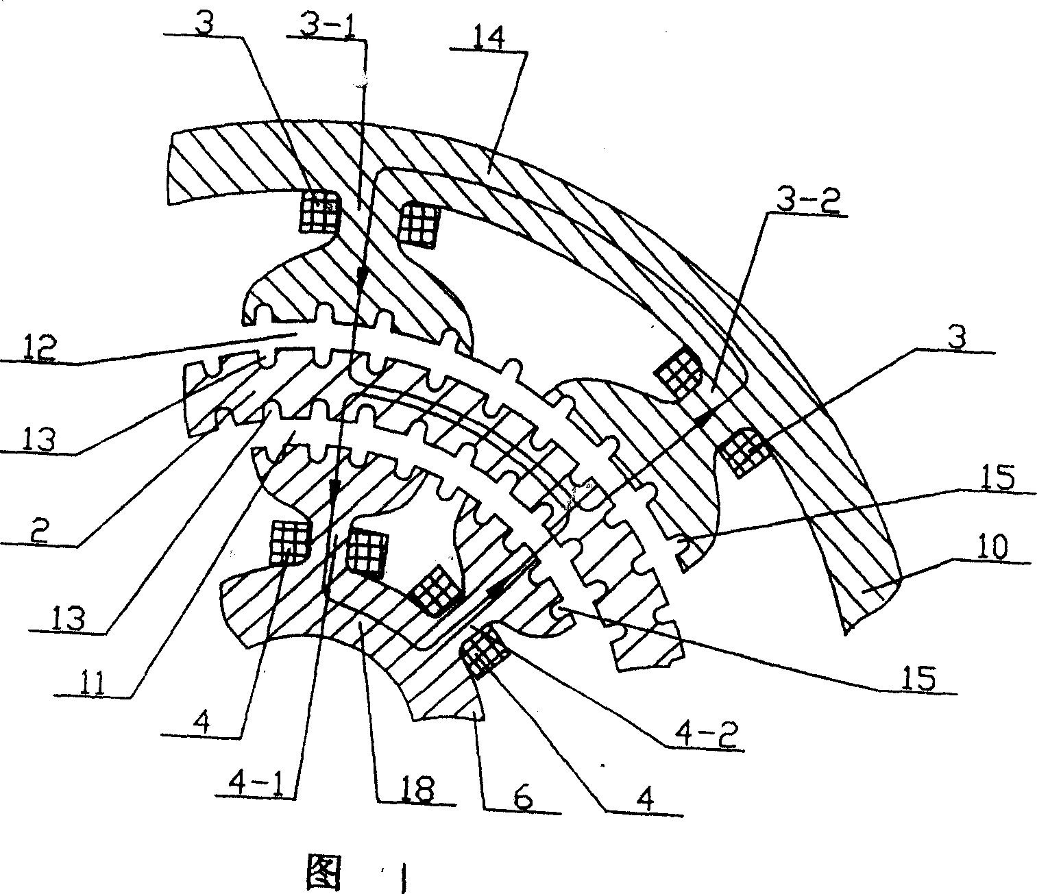
[0007] Embodiment: The annular permanent magnet 1 that is filled with the magnetic field in the axial direction is arranged in the middle part of the rotor core 2 in the length direction of the silicon steel sheets, and the rotor core is divided into a left end iron core 2-1 and a right end iron core 2-2. There are cogs 13 evenly distributed along the circumference and parallel to the axis on the surface of the inner hole and the outer circle. One-half the space between the slots, the outer circle of the rotor core and the inner circle of the outer stator core form an outer air gap 12, the inner circle of the rotor core and the outer circle of the inner stator core 6 form an inner air gap 11, and the outer stator made of silicon steel sheets The inner circle of the iron core 10 and the outer circle of the inner stator core are respectively provided with tooth slots 15 uniformly distributed along the circumference and parallel to the axis line, and the outer stator excitation wi...


PUM


Abstract

A direct drive reluctance machine is provided. An outer air gap is formed between the outer annulus of a rotor core and the inner annulus of an outer stator core formed by the stacking of silicon sheets; an inner air gap is formed between the inner annulus of the rotor core and the outer annulus of an inner stator core; keywalls are arranged in the inner annulus of the outer stator core and in the outer annulus of the inner stator core; the inner annulus of the outer stator core and the outer annulus of the inner stator core are respectively provided with an outer stator field copper and an inner stator field copper; a rotor cage of non-permeablility magnetic material is fixed on a shaft to support the rotor core; the shaft is embedded in the inner bore of the inner stator core through a bearing; a toroidal permanent magnet which is axially provided with a magnetic field is arranged in the lengthwise center of the rotor core and divides the rotor core into a left end iron core and a right end iron core; keywalls are respectively arranged in the inner bore and the outer annulus of the rotor core; the keywalls on the left iron core stagger one-half of tooth space with the keywalls on the right iron core circumferentially. The invention has the advantages of small cubage, light weight and reduced excitation consumption.

Description

technical field [0001] The present invention relates to a direct drive reluctance motor. Background technique [0002] The stator and rotor of the existing direct-drive reluctance motors do not use permanent magnet materials. In order to obtain high power, large excitation power is required, which limits the performance-to-volume ratio of the motor and increases the cost of the drive system. Contents of the invention [0003] The purpose of the present invention is to overcome the above defects and provide a direct drive reluctance motor. [0004] The technical solution of the present invention is: a direct drive reluctance motor, characterized in that: the outer circle of the rotor core made of silicon steel sheets and the inner circle of the outer stator core made of silicon steel sheets form an outer air gap, and the inner circle of the rotor core and the inner circle of the outer stator core made of silicon steel sheets The inner air gap is formed between the outer ci...

Claims


Application Information

Patent Timeline
Patent Type & Authority Applications(China)
IPC IPC(8): H02K16/04H02K21/12H02K29/00H02K1/14H02K1/27
Inventor 马长富
Owner TIANJIN DEXIN ELECTRIC MACHINERY
Why Eureka
Try Eureka