Resonance converter and its synchronous commutation driving method

A resonant converter, synchronous rectification technology, applied in high-efficiency power electronic conversion, output power conversion devices, conversion equipment with intermediate conversion to AC, etc. lower problem

Active Publication Date: 2008-04-02
DELTA ELECTRONICS INC
View PDF0 Cites 28 Cited by
  • Summary
  • Abstract
  • Description
  • Claims
  • Application Information

AI Technical Summary

Problems solved by technology

However, since V ds (on) The voltage amplitude is very low, in order to achieve the best synchronous rectification driving effect, the reference voltage value V ref Must be low to be easily affected by interference
Especially when the LLC circuit is working at light load, starting, dy

Method used


Image

  • Resonance converter and its synchronous commutation driving method
  • Resonance converter and its synchronous commutation driving method
  • Resonance converter and its synchronous commutation driving method

Examples


Embodiment Construction

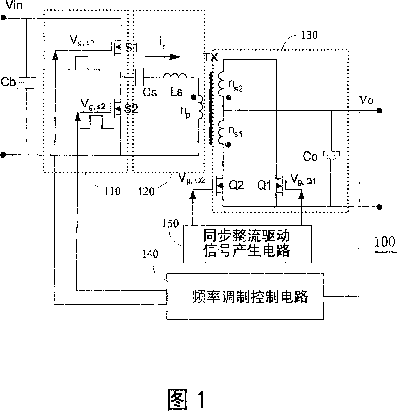
[0062] Please refer to FIG. 6, which is a circuit diagram of the first synchronous rectification driving scheme of the LLC series resonant converter proposed by the present invention. Compared with FIG. 1, the same circuit elements are marked with the same reference numerals, which are not mentioned here To repeat. However, it should be noted that although a half-bridge circuit with only one bridge arm is used to form the switch circuit at the input end in FIG. 6 , a full-bridge circuit with two bridge arms can also be used to form the switch circuit at the input end. In addition, although the circuits in the embodiments all use transistor switches as switching elements, this does not affect the various variant examples in which the superordinate concept is defined by "switch" in the scope of the claims. In addition, a synchronous rectification drive circuit 60 is additionally installed in the LLC series resonant converter 600 to implement the synchronous rectification drive m...


PUM


Abstract

The present invention provides a resonance converter and the synchronous rectifying driving method thereof, the resonance converter includes a switching circuit which is composed of at least two first switches, a resonant circuit with resonance frequency, a transformer, and a full wave circuit which is composed of two second switches, wherein each second switch will equally generate channel resistance electric voltage when the current flows through the source and drain, the synchronous rectifying driving method comprises the following procedures: doing comparison to the reference voltage aiming at the channel resistance to drive each second switch of the full wave circuit when the working frequency of the resonance converter is less than the resonance frequency and the resonance converter is connected to the heavy duty; and driving each second switch of the full wave circuit with the identical signal which is respectively drive each first switch when the working frequency of the resonance converter is larger or equal to the resonance frequency. The invention can prevent the generating of the phenomenon that each switch in the synchronous rectifying circuit is incorrectly driven.

Description

technical field [0001] The invention relates to a resonant converter and a synchronous rectification driving method thereof, in particular to an LLC series resonant converter applied to a power supply. Background technique [0002] Please refer to FIG. 1, which is a circuit diagram of an LLC series resonant converter composed of synchronous rectification transistors in the prior art, wherein the LLC series resonant converter 100 is mainly composed of a switch circuit 110, a resonant circuit 120, a transformer TX, and all composed of wave rectification circuit 130. [0003] In the LLC series resonant converter 100 , the switch circuit 110 can be a half-bridge circuit composed of a pair of power transistors S1 and S2 in FIG. 1 , or a full-bridge circuit. In addition, the resonant circuit 120 is composed of the series resonant inductor Ls, the series resonant capacitor Cs, and the magnetizing inductance Lm of the transformer TX; of course, for those skilled in the art, the ser...

Claims


Application Information

Patent Timeline
IPC IPC(8): H02M3/28H02M3/335H02M7/5387
CPCY02B70/1433Y02B70/1475Y02B70/1441Y02B70/10Y02P80/10
Inventor 陶洪山甘鸿坚应建平
Owner DELTA ELECTRONICS INC
Why Eureka
Try Eureka