Moisture-repellent protective layer for a winding head of an electric machine

A technology of end winding and protective layer, which is applied in the direction of winding, winding insulation shape/style/structure, electric components, etc. It can solve the problems of easy formation of cracks and motor damage, so as to prolong the service life and reduce the difficulty of cleaning work. Effect

Inactive Publication Date: 2008-04-02
SIEMENS AG
View PDF1 Cites 5 Cited by
  • Summary
  • Abstract
  • Description
  • Claims
  • Application Information

AI Technical Summary

Problems solved by technology

This known protective layer is prone to cracks, for example in the event of temperature changes, at least partia...

Method used


Image

  • Moisture-repellent protective layer for a winding head of an electric machine
  • Moisture-repellent protective layer for a winding head of an electric machine

Examples


Embodiment Construction

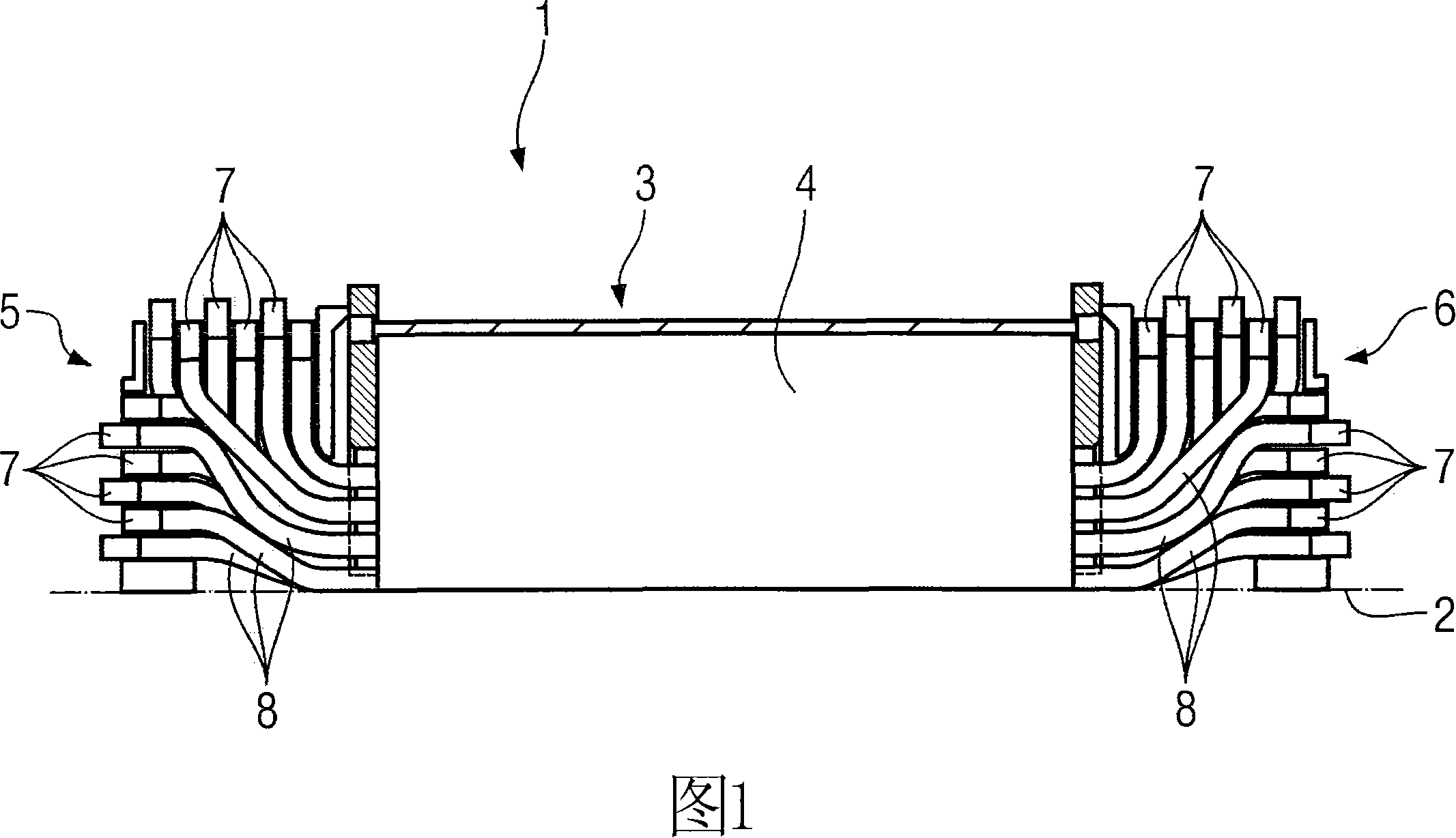
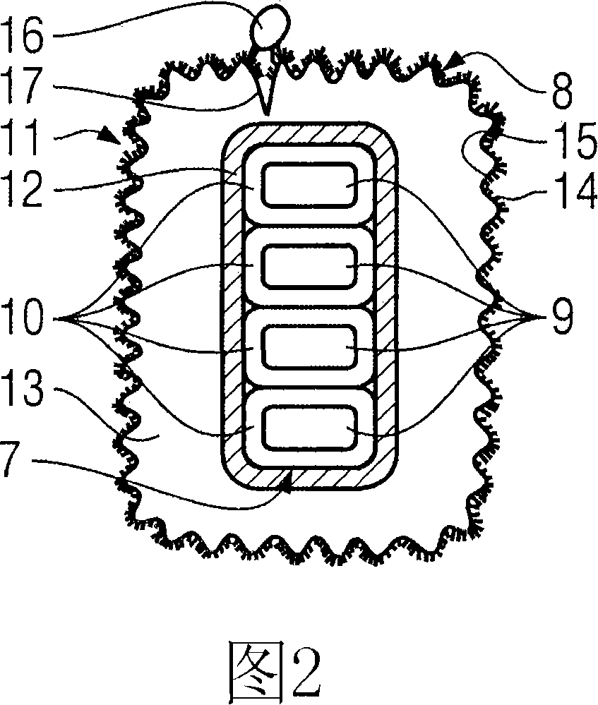
[0021] The same components are denoted by the same reference symbols in both Fig. 1 and Fig. 2 .

[0022] FIG. 1 shows an exemplary embodiment of an electric machine 1 in a partial cross-sectional view. The sectional view of the motor 1 is in fact a sectional view of a stator 3 of the motor 1 taken along the axis of rotation 2 , but only the upper half of the stator 3 is shown. FIG. 1 does not show the area 4 with the stator core laminations and the electrical coil conductors embedded in the slots in detail, but only shows this active area in schematic form. The two end windings 5 ​​and 6 which the stator 3 has are respectively arranged on both axial sides of the active region 4 .

[0023] The end windings 5 ​​and 6 consist of a plurality of electrical conductor arrangements 7 leading out of the stator laminate core in the direction of the axis of rotation 2 . The coil winding is formed by a suitable electrical connection of the conductor arrangement 7 in the region of the e...


PUM

PropertyMeasurementUnit
The average particle sizeaaaaaaaaaa

Abstract

The invention relates to a protective layer (13) for a winding head of an electric machine. Said protective layer consists of a moisture-repellent material that comprises a nanostructured surface (8) once it has been applied to the winding head, resulting in a water contact angle of at least 120 DEG .

Description

technical field [0001] The invention relates to a protective layer for the end winding of an electrical machine. Background technique [0002] Such protective layers, which are arranged on the end windings of an electrical machine (for example in the form of an electric motor or generator), have the effect of electrical insulation, mechanical protection, chemical protection or moisture protection. Known protective layers are produced by partial multiple impregnation with filling resins and impregnating varnishes, or by casting with inorganic filling resins (casting resins). [0003] DE 3133734 C2 describes a protective layer made of a hard coating of silicone elastomer, for example an organomodified silicone rubber material curable at room temperature. This known protective layer is prone to cracks, for example, when the temperature changes, and delamination occurs at least locally, allowing moisture to penetrate through the cracks generated, causing a large degree of damag...

Claims


Application Information

Patent Timeline
IPC IPC(8): H02K3/30
CPCH02K3/38H02K3/44Y10T428/24802Y10T428/24893
Inventor 伯恩哈德·克劳斯纳亚历山大·莫勒
Owner SIEMENS AG
Why Eureka
Try Eureka