
Automobile production line sling and regulating method thereof

A technology of automobile production line and spreader, which is applied in the direction of load hanging components, transportation and packaging, etc. It can solve the problems of reducing equipment utilization, operability, and market competitiveness, so as to reduce equipment investment costs and reduce adjustments Working hours, the effect of improving equipment utilization

Inactive Publication Date: 2008-04-09
CHERY AUTOMOBILE CO LTD
View PDF0 Cites 5 Cited by
  • Summary
  • Abstract
  • Description
  • Claims
  • Application Information

AI Technical Summary

Problems solved by technology

At present, the rear support arm of the domestic automobile spreader is basically still welded directly to the rear support arm with the support plate of the rear support block, which makes it difficult for the spreader to adapt to the needs of multiple vehicle models.
That is to say, the automobile spreader of the current production line cannot directly and effectively adapt to the mixed line production of multiple models.
At present, the bracket support plate of the auto spreader on the automobile production line is directly welded and fixed to the bracket arm of the spreader. This fixed connection method will easily lead to deviations in the relative positioning of the bracket and the side skirt of the vehicle body, which can only be rough. The relative positioning of the ground, this kind of rough relative positioning makes the car body sometimes cannot be completely hoisted by the spreader, which is easy to cause safety accidents and affects the assembly quality of the vehicle
[0003] When changing the model of the automobile production line, it is necessary to carry out large-scale transformation of the spreader on the production line in advance. This large-scale transformation not only wastes a lot of manpower, material resources and financial resources, but also greatly reduces the utilization rate of the equipment.
When automobile manufacturers develop new models, due to changes in the width of the car body, the existing spreaders cannot be used for the new models, so they have to spend a lot of manpower and material resources to modify the existing spreaders, or even build new ones to adapt to other models. The production line of different vehicle types, and the position of the modified bracket can only meet one body width. If another type of vehicle body width is changed, the position of the bracket of the spreader may not be used again.
In addition, such a change not only consumes a lot of manpower, financial and material resources, but also greatly delays the time for car manufacturers to launch the latest car products, reducing market competitiveness.
Although some manufacturers have also made some changes to the spreader bracket, they can basically only meet the mixed production of one or two models, or although they can meet the requirements of mixed production of multiple models, the operability is greatly reduced and the Reduced efficiency

Method used


Image

  • Automobile production line sling and regulating method thereof
  • Automobile production line sling and regulating method thereof

Examples


Embodiment 1

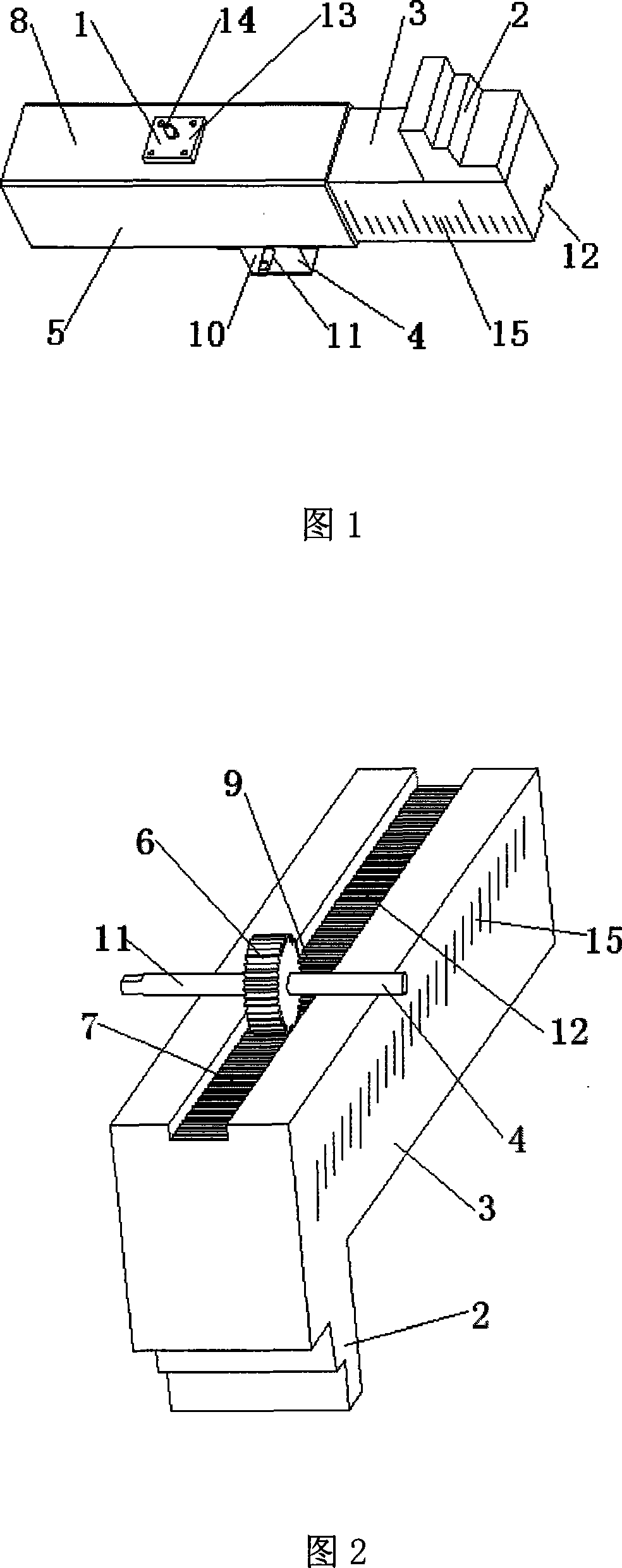
[0031] As shown in Fig. 1 and Fig. 2, on the basis of the above-mentioned technical solution, the cross-sectional shape of the mating surface of the supporting arm fixing frame 5 and the movable supporting arm 3 using a clearance fit according to the present invention is rectangular. The movable support arm 3 is inserted into the rectangular hole of the support arm fixed mount 5 and forms a clearance fit. The movable support arm 3 can be freely expanded and contracted in the rectangular hole of the supported arm fixed mount 5, and will not rotate during the telescopic process, so that the support arm The position of the block 2 on the straight line of motion will not change due to movement, ensuring that it can hold up the vehicle body reliably.

Embodiment 2

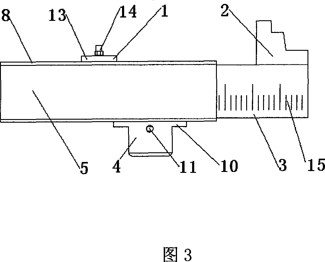
[0033] As shown in Figure 2, on the basis of Embodiment 1, the rear transverse boom 8 of the present invention is provided with a stroke adjuster 4, and the stroke adjuster 4 is located between the bracket arm fixture 5 and the movable bracket arm. 3 is provided with a rack and pinion transmission mechanism 9, and the transmission direction of the rack and pinion transmission mechanism 9 is to make the movable support arm 3 stretch out or retract on the support arm fixed frame 5. The rack and pinion transmission mechanism 9 is used to adjust the position of the movable support arm 3, which is convenient to operate, labor-saving, easy to control, accurate in positioning, and the structure occupies a small space.

Embodiment 3

[0035] As shown in Figure 2, the structure of the rack and pinion transmission mechanism 9 described in the above-mentioned embodiment is: a rack 7 is set on the body of the movable support arm 3, and a gear 6 is established on the support arm fixed frame 5. The gear 6 is supported by the stroke adjuster bracket 10 provided on the stroke adjuster 4 through the gear adjustment shaft 11, and the gear 6 and the rack 7 are meshed with each other. This setting scheme mainly considers the support of the gear 6 conveniently, and it is also convenient to use the gear 6 to carry out the adjustment operation.


PUM


Abstract

The invention discloses an automobile production line lifting tool and comprises a suspender, a front transverse lifting arm and a back transverse lifting arm (8). The back transverse lifting arm (8) is provided with a corbel fast headstock (5) and a movable corbel (3). The movable corbel (3) is inserted in the corbel fast headstock (5) to form clearance fit. The extension end of the movable corbel (3) is provided with a follow block (2). The back transverse lifting arm (8) is provided with a movable corbel fixer (1) which can fasten or loose the corbel fast headstock (5) and the movable corbel (3). The above mentioned technical scheme ensures that the automobile production line lifting tool has the ability of quick, flexible and accurate adjustment to adapt to mixing line production of different vehicle styles. The invention also discloses a regulation method adopted by the automobile production line lifting tool.

Description

technical field [0001] The invention belongs to the technical field of automobile manufacturing, and relates to automobile production process equipment in this field. More specifically, the invention relates to a hanger for an automobile production line. In addition, the present invention also relates to the adjustment method adopted by the above-mentioned automobile production line hanger. Background technique [0002] In the production line, automobile manufacturing enterprises use spreaders to lift the car body for processing and assembly operations. At present, the rear support arm of the domestic automobile spreader basically stays on the rear support block support plate directly welded on the rear support arm, which makes it difficult for the spreader to adapt to the changing needs of multiple models. That is to say, the automobile spreader of the current production line cannot directly and effectively adapt to the mixed line production of multiple models. At present...

Claims


Application Information

Patent Timeline
IPC IPC(8): B66C1/10
Inventor 张旭东
Owner CHERY AUTOMOBILE CO LTD
Learn More