
Apparatus for precisely controlling wire distribution distance

A technology of precise control and wiring, applied in microstructure devices, piezoelectric/electrostrictive/magnetostrictive devices, membrane technology, etc., can solve the problems of high production cost, high wiring cost, and cost increase, and achieve low cost , Easy to operate, easy to achieve effect

Inactive Publication Date: 2008-04-09
CHONGQING UNIV
View PDF1 Cites 0 Cited by
  • Summary
  • Abstract
  • Description
  • Claims
  • Application Information

AI Technical Summary

Problems solved by technology

However, because it uses a mold for auxiliary positioning of fibers, the density and accuracy of fiber arrangement are bound to be subject to the processing accuracy of the mold. The processing technology and precision of the mold directly restrict the minimum spacing of the fiber arrangement, and with the spacing The continuous reduction of the mold processing cost will also increase exponentially
In addition, the structure of the device is relatively complicated, the production cost is high, and the volume is also relatively large. The application range of this device will also have many restrictions.
[0004] Obviously, in the arrangement of fibers or microfilaments, the existing public technology has not yet reached a good coordination plan on how to effectively control the wiring spacing and equipment manufacturing costs. The more complex the instrument and equipment, the higher the wiring cost, which correspondingly increases the manufacturing cost of subsequent microsystem functional devices

Method used


Image

  • Apparatus for precisely controlling wire distribution distance
  • Apparatus for precisely controlling wire distribution distance
  • Apparatus for precisely controlling wire distribution distance

Examples


Embodiment 1

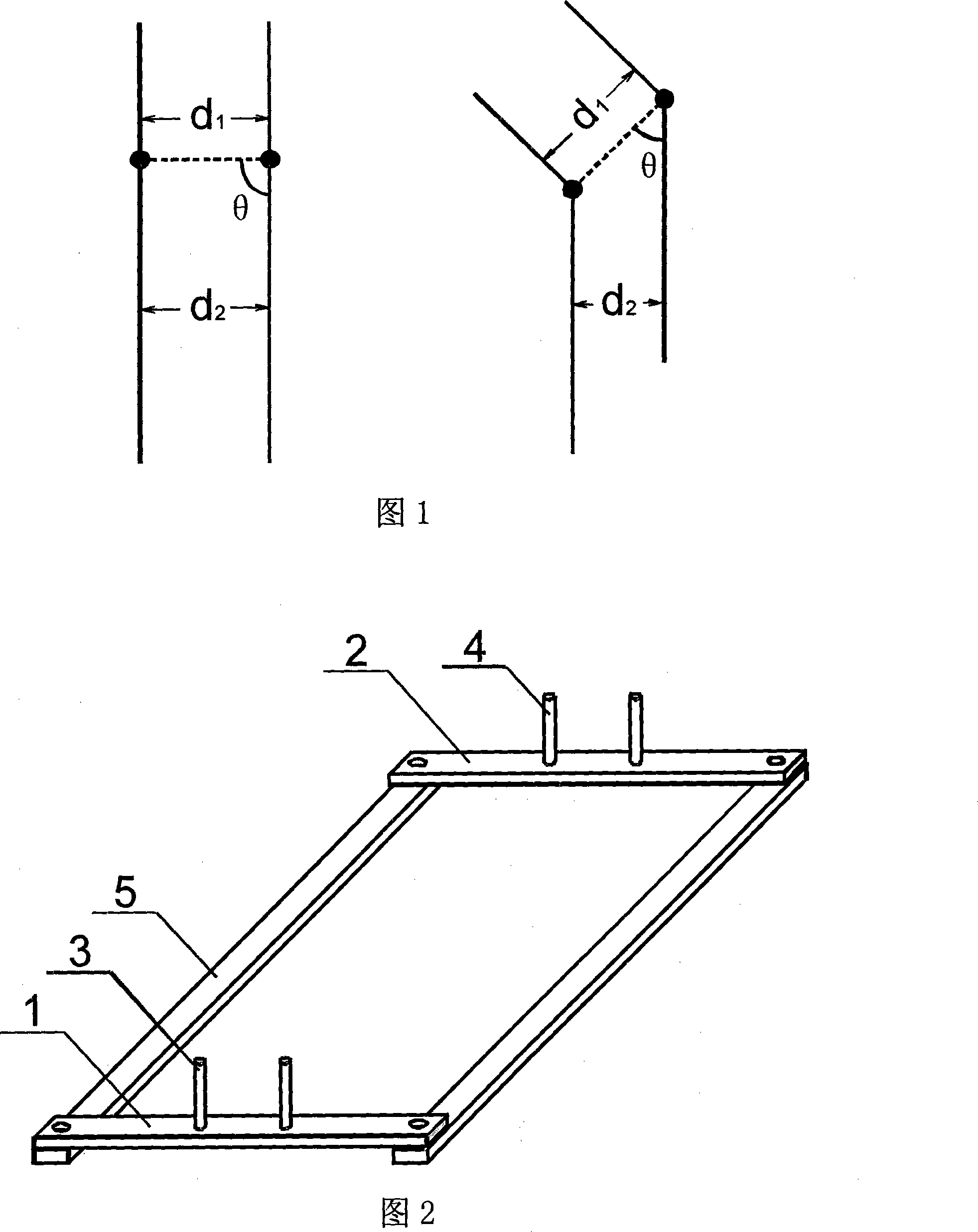
[0030] As shown in Figure 2: the device is a two-line spacing control device, consisting of two strip-shaped wiring pillows (wiring pillow A 1 and wiring pillow B 2) and two straight rods 5 to form a parallelogram frame, each wiring pillow is respectively The wiring comb (wiring comb A 3 and wiring comb B 4) is composed of two cylinders, and the distance between the cylinders of each wiring comb is equal. This device enables high-precision control of the spacing between two parallel lines. In the microscopic observation environment, the minimum distance between two lines can be controlled at the submicron level.

Embodiment 2

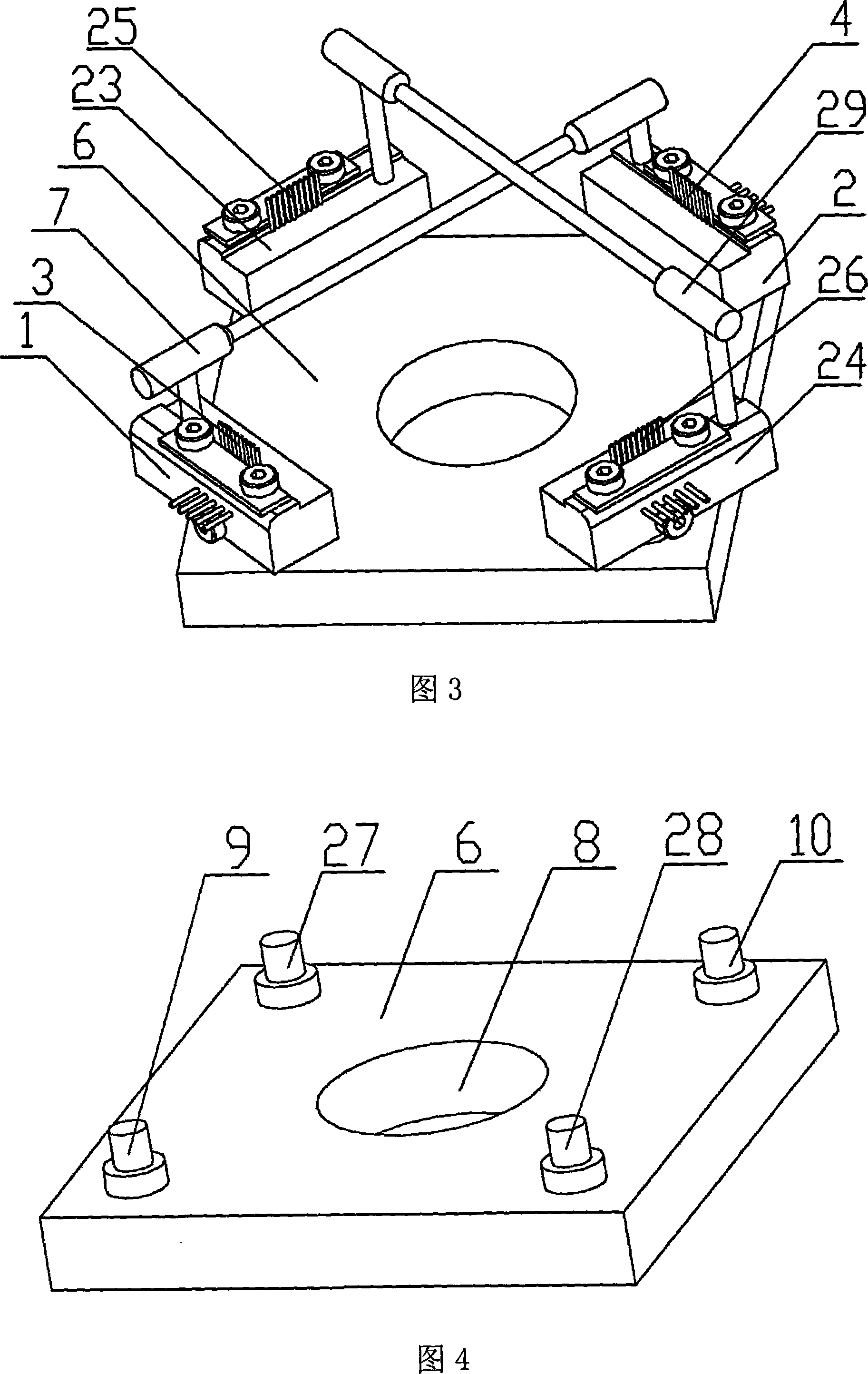
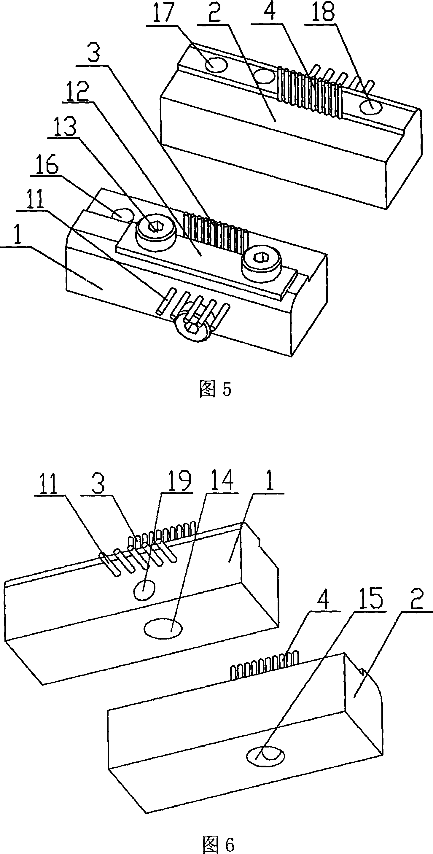
[0032] As shown in Figures 3 to 9: the device is an orthogonal wiring spacing control device, which consists of two pairs of opposing wiring pillows (wiring pillow A 1 and wiring pillow B 2, wiring pillow C 23 and wiring pillow D 24), two Composition of wiring combs (wiring comb A 3 and wiring comb B 4, wiring comb C 25 and wiring comb D 26), base 6, connecting rod (connecting rod 7 and second connecting rod 29), and form two parallelogram frames . Base 6 is equipped with operating hole 8 and two pairs of rotating shafts (rotating shaft first 9 and rotating shaft second 10, rotating shaft third 27 and rotating shaft D 28). The operation hole 8 is located at the center of the base 6, and the two connecting lines between the two pairs of rotating shafts are orthogonal to each other. The wiring comb is composed of ten cylinders with a diameter of 0.63 mm and a center distance of 1 mm. Each wiring comb is fixed on the top of the corresponding wiring pillow.

[0033] One group of...

Embodiment 3

[0037] As shown in Figures 10 to 12: the device is a wiring array spacing control device with variable wiring length, consisting of wiring pillows (wiring pillow A 1 and wiring pillow B 2), wiring combs (wiring comb A 3 and wiring comb B 4 ), straight bar 5, connecting rod 20, slide block 21 and wiring board 22 constitute. The wiring pillow is strip-shaped, and two straight bars 5, a connecting rod 20 and the wiring pillow B 2 form a parallelogram frame. A slide block 21 is provided on the straight bar 5 and can slide freely along the straight bar 5. The two slide blocks 21 are movably connected with the wiring pillow armor 1, and the two wiring pillows are parallel to each other. The two wiring combs are composed of ten wiring posts arranged at equal intervals. There are small holes on the wiring pillow to fix the wiring combs. The wiring board 22 runs through the wiring combs.

[0038] When wiring, the effective length of the wiring can be adjusted by sliding the slider, an...


PUM


Abstract

The invention provides an accurately controlling routing interval device. The device can be used for routing interval accurate control in micromachining technosphere. The device includes at least one movable parallelogram lever. Every parallelogram lever consists of two opposite routing pillows and two connectors. The routing pillow is fixed with a routing comb. Wires are routed in a parallel routing array formed between the routing combs on two opposite routing pillows, and then the vertex angle degree of the parallelogram lever is quantificationally changed, thereby accurately controlling routing interval. The device has the advantages that the structure is simple, the realization is easy, the operation is convenient, the cost is low and the device is steady and reliable. Accurately controlling routing interval can be implemented and the controlling precision can reach micron-grade or submicron-grade. The device provides an advantaged tool for the routing interval accurate control in the micromachining technosphere.

Description

Technical field: [0001] The invention belongs to the technical field of wiring in the micromachining technology, and in particular relates to the precise control technology of micron-level or sub-micron-level wiring spacing between microwires. Background technique: [0002] Some occasions of microsystem technology require precise arrangement of micro-sized fibers or microwires, for example, arranging fibers into arrays with very small pitches for processing and fixing tiny devices, or densely packing metal wires to make microelectrode arrays, and Micro-scale measurement and calibration, etc. Furthermore, microchannels and their arrays can be fabricated by some soft engraving processes after the fibers or microfilaments are precisely arranged, which is also an important development direction of micromachining technology. In the process of realizing these technologies, an important technical feature is that the arrangement accuracy of fibers or microfilaments is relatively hi...

Claims


Application Information

Patent Timeline
Patent Type & Authority Applications(China)
IPC IPC(8): B81C5/00B81C99/00
Inventor 贾月飞蒋家欢蔡坤宝蔡绍皙宋国立
Owner CHONGQING UNIV
Learn More