
Hollow hammer hole bottom strong suction apparatus

The technology of a suction device and a down-the-hole hammer is applied in percussion drilling, reciprocating drilling rigs, drilling equipment and methods, etc., and can solve problems such as loss of drilled ore samples with reduced diameters

Inactive Publication Date: 2008-04-09
JILIN UNIV
View PDF0 Cites 21 Cited by
  • Summary
  • Abstract
  • Description
  • Claims
  • Application Information

AI Technical Summary

Problems solved by technology

[0005] The purpose of the present invention is to address the above-mentioned deficiencies in the prior art and provide a method to solve the problems of diameter reduction, drill pinching and partial ore sample loss caused by a part of the gas carrying small particles of cuttings and rock powder escaping from the annular gap outside the borehole. The strong suction device at the bottom of the through-type DTH hammer

Method used


Image

  • Hollow hammer hole bottom strong suction apparatus

Examples


Embodiment Construction

[0013] Below in conjunction with accompanying drawing and example, the present invention is described in further detail:

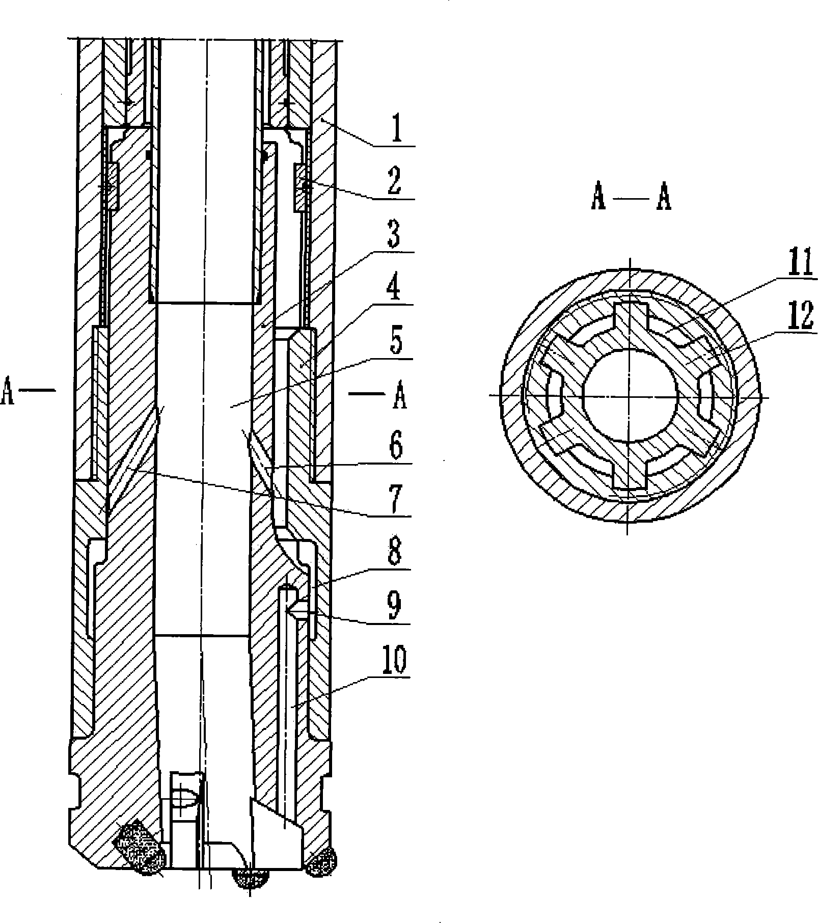
[0014] The outer cylinder 1 of the down-the-hole hammer is connected with the lower joint 4 through a screw, the inner wall of the lower part of the lower joint 4 is provided with a ring groove 8, the lower section of the reverse circulation drill bit 3 is provided with a meridian hole 9 and communicates with the bottom nozzle hole 10, and the middle part of the reverse circulation drill bit 3 is provided with a radial hole 9. There are drill spline grooves 11 and drill splines 12. There are more than 2 normally open inner spray holes 6 at the bottom of the drill bit spline groove 11, and more than 2 spare inner spray holes 7 are arranged on the top of the drill bit spline 12. The hole 6 and the spare inner spray hole 7 communicate with the central channel 5 .

[0015] The angle between the axis of the normally open inner spray hole 6 and the axis of the s...


PUM


Abstract

The invention discloses a drill machine used for drilling gas-oil well hard rock or others, in particular to a strong pumping device used for a pneumatic through down-hole hammer-hole bottom. The device mainly adopts an annular groove arranged on an inner wall of a lower part of a lower adapter. And a radial hole communicated with a bottom nozzle hole is arranged on a lower section of an anti-circulation bore. A bore spline groove and a spline are arranged in the middle of the anti-circulation bore. More than one normal-open inner nozzle holes are arranged at the bottom of the spline groove, and spare inner nozzle holes are arranged on the spline. The normal-open inner nozzle hole and the spare inner nozzle holes are respectively communicated with a central through-hole. When in a normal drilling process, the radial hole is communicated with the annular groove of the lower part of the lower adapter. When the drilling tool is lifted, the anti-circulation bore slides downwards, and the air flow cannot be blown to an under-hole stratum through the bottom nozzle hole as the radial hole is closed by the inner wall of the lower part of the lower adapter. The invention changes the existing through down-hole hammer-hole slag-draining mode and solves the problem that a part of air containing rock granules and powders overflows from outer annular clearances of the bore to lead to the loss of reduction, clamp drill and partial core samples.

Description

technical field [0001] The invention relates to hard rock drilling and other drilling equipment for oil and gas wells, in particular to a through-type pneumatic down-the-hole hammer hole bottom powerful suction device. Background technique [0002] Through-type DTH hammer reverse circulation continuous coring technology is an advanced drilling technology. Its working principle is: the compressed air enters the DTH hammer through the outer ring channel of the double-wall drill pipe to drive the piston to do work, and the exhaust gas after the work passes through the reverse circulation drill bit of the multi-nozzle principle to generate a negative pressure area at the bottom of the hole, forming a full-hole reverse circulation. . Due to the high recovery rate of rock cores, full-hole reverse circulation and little stratum disturbance, this process has great advantages in solving drilling problems in complex strata. In recent years, tests have been carried out in formations ...

Claims


Application Information

Patent Timeline
IPC IPC(8): E21B1/38
Inventor 彭梘明王茂森殷其雷刘建林博坤范黎明张永光
Owner JILIN UNIV
Learn More