Whorl structure recognition method based on wavelet transformation and supporting vectors machine

A support vector machine and wavelet transform technology, applied in the field of vortex structure recognition, can solve the problems of feature redundancy, low recognition rate, and large amount of calculation

Inactive Publication Date: 2008-04-09
BEIHANG UNIV
View PDF0 Cites 9 Cited by
  • Summary
  • Abstract
  • Description
  • Claims
  • Application Information

AI Technical Summary

Problems solved by technology

The traditional vortex structure identification method, in terms of feature extraction, is usually based on the multi-resolution analysis characteristics of wavelet transform, and directly performs wavelet decomposition, using the wavelet coefficient matrix as a feature quantity to...

Method used

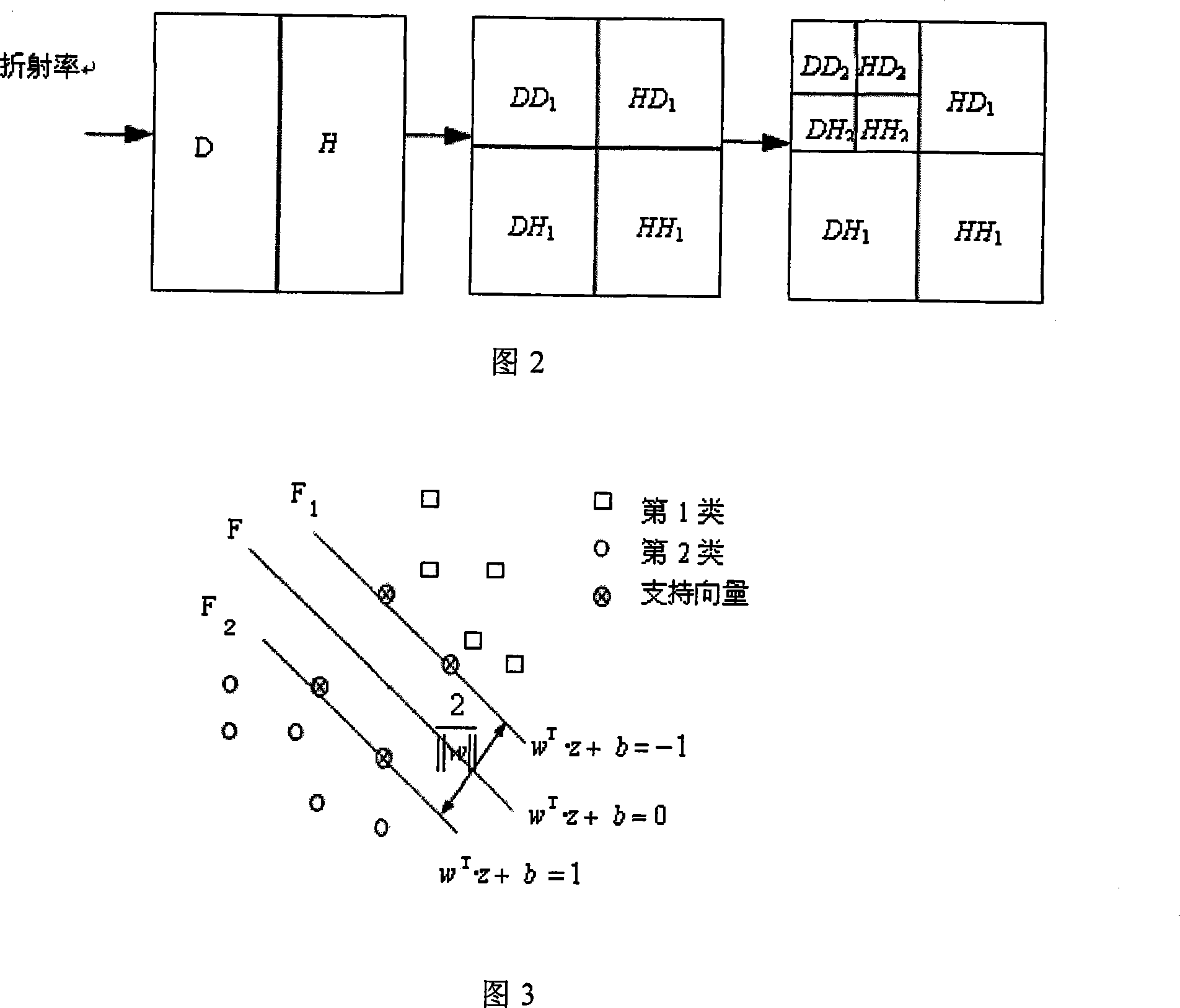

Image

  • Whorl structure recognition method based on wavelet transformation and supporting vectors machine
  • Whorl structure recognition method based on wavelet transformation and supporting vectors machine
  • Whorl structure recognition method based on wavelet transformation and supporting vectors machine

Examples


Embodiment L3

[0022] The wavelet decomposition process is to determine {a n,m}, {b n,m}-L 1 ≤n≤0, -L 2 ≤ m ≤ 0, {a n,m}, {b n,m} is the truncation of the infinite sequence, and the two sequences can be obtained by the existing wavelet analysis method. L 1 , L 2 Equivalent to the size of the filtering window, L 1 =L 2 =2N-1. For known refractive index field data [c k;n,m], k=N-1, ... N-M; -L 3 (k) ≤n≤L 4 (k) ;-L 5 (k) m≤L 6 (k) , where k is the level of decomposition, L 3 , L 4 Indicates the number of rows at the start and end of the data, respectively; L 5 , L 6 Indicates the start and end column numbers of the data, respectively. This example L 3 (N) =L 4 (N) =L 6 (N) =128. make L 3 ( k ) = L 3 ( k + 1 ) / 2 ...


PUM


Abstract

The invention relates to a vortex structure recognition method based on Support Vector Machine (SVM), in aspect of feature extraction, statistics of coefficient matrix from wavelet transform of refractive index filed data is extracted, compared with traditional method of utilizing coefficient matrix from wavelet transform directly, the method winkles mass of redundant information, and decreases calculating amount. In aspect of classifier design, classification method based on support vector machine is brought forward, minimum structural risk principle is utilized to ensure that the vortex structure is correctly detached by classification surface and the classification interval is made maximum, in theory the invention decreases mis-recognition rate compared with the traditional classification method based on minimum experiential risk principle. The invention can represent and distinguish turbulence vortex structure more accurately; the invention establishes bases of optics effect accuracy for airborne optical equipment of missiles and airplanes, etc.

Description

technical field [0001] The invention relates to a vortex structure recognition method based on wavelet transform and support vector machine, which can be used to analyze the aero-optical effect formed between the optical hood and the incoming flow of missiles and aircraft flying at high speed in the atmosphere, and is used for image correction and turbulence control. Provide the basis. Background technique [0002] When high-speed imaging-guided missiles and aircraft fly at high speed in the atmosphere, a high-speed and complex flow field will be formed around the optical head cover, causing the phase of the target light wave to change when it passes through the high-speed flow field, and the target image will be shifted, blurred, shaken, and energy attenuated. , this phenomenon is called the aero-optic effect. One of the research focuses of aero-optical effects is the relationship between distorted wavefront and turbulent vortex dynamics. According to the vortex theory of...

Claims


Application Information

Patent Timeline
IPC IPC(8): G01M9/00G01M9/06G01M11/00G01M11/02
Inventor 杨照华房建成吴琳冯浩楠
Owner BEIHANG UNIV
Why Eureka
Try Eureka