

Cylinder-shaped polyphase linear permanent-magnet synchronous generator
A permanent magnet synchronous motor, cylindrical technology, applied in the direction of electrical components, electromechanical devices, electric components, etc., can solve the problem of limited selection, achieve the effect of improving the performance volume ratio, facilitating the processing technology, and increasing the output thrust
- Summary
- Abstract
- Description
- Claims
- Application Information
AI Technical Summary
Problems solved by technology
Method used
Image

Examples
specific Embodiment approach 1
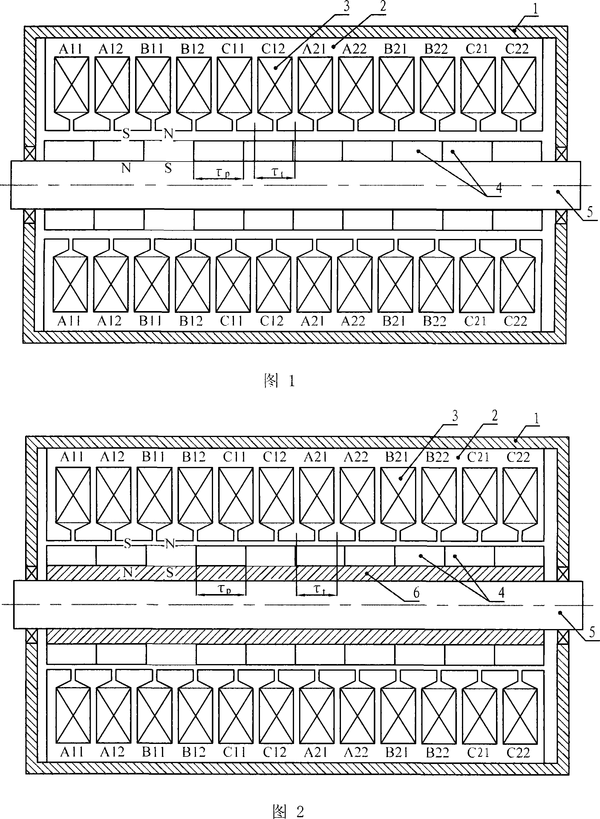
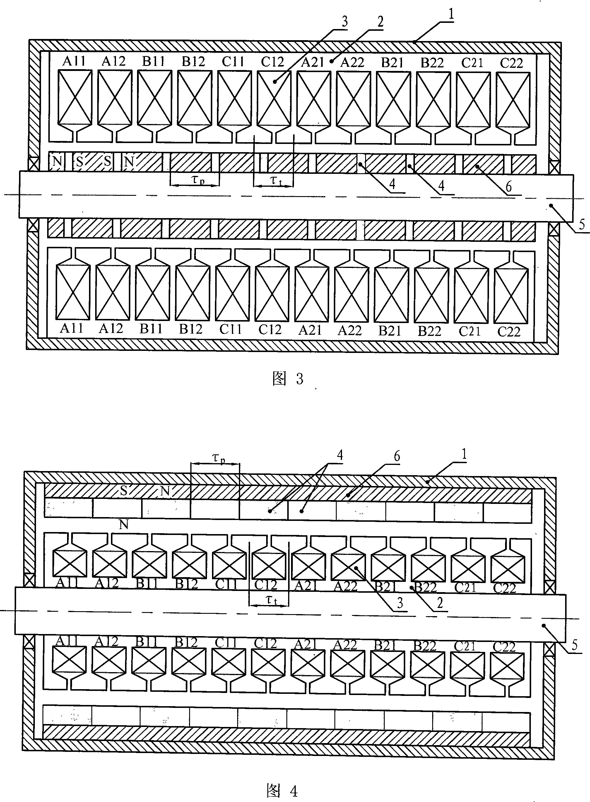
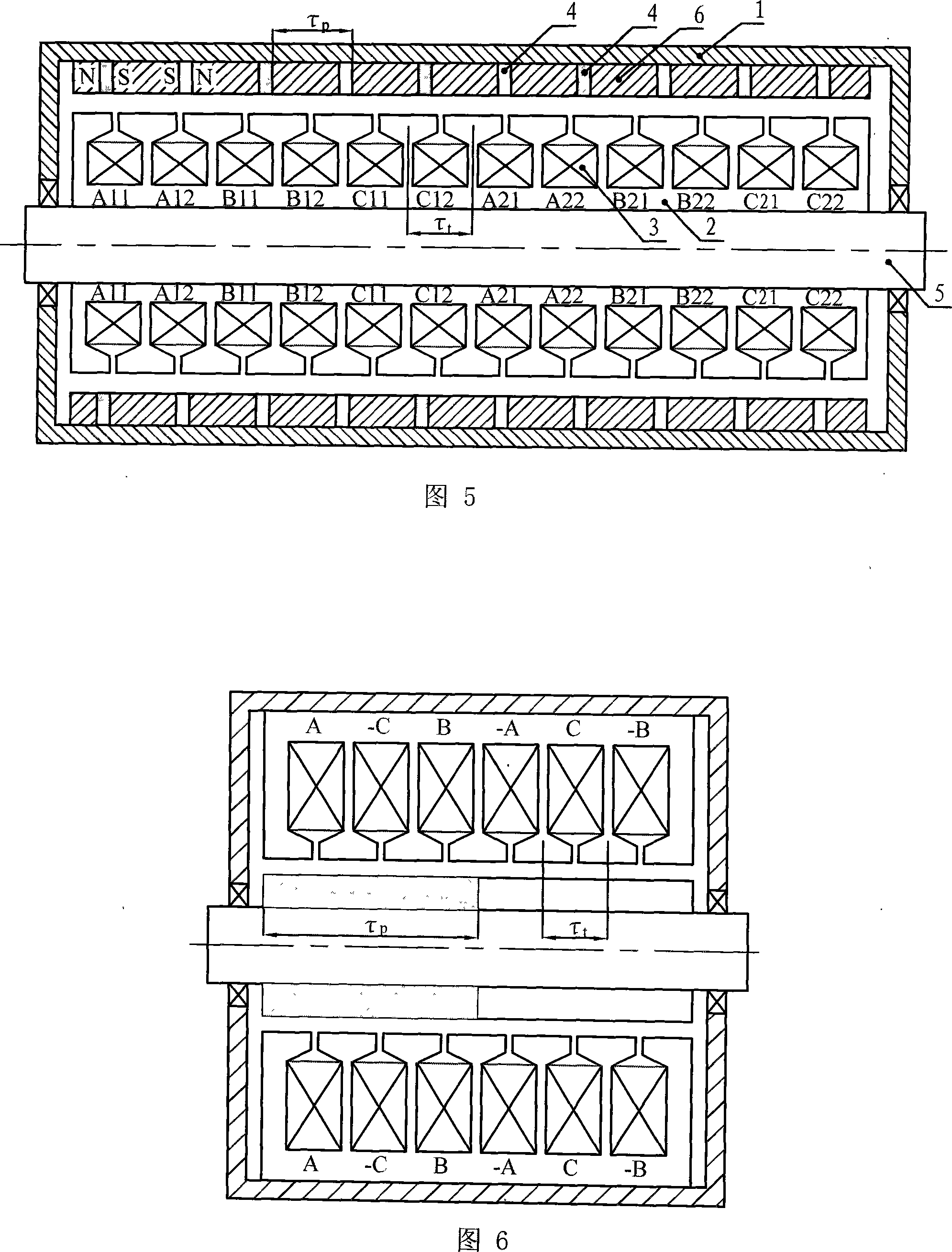
[0009] Specific embodiment one: the cylindrical multi-phase linear permanent magnet synchronous motor of this embodiment includes a primary, a secondary and an air gap, the primary includes an armature core 2 and an armature winding 3, and the armature core 2 is circular, The armature winding 3 is embedded in the slot of the armature core 2, the secondary includes a permanent magnet 4, the permanent magnet 4 is a ring structure, and the tooth pitch τ of the armature core 2 t The pole distance τ from the permanent magnet 4 p Satisfy 0.8τ between t ≤τ p ≤1.2τ t , and τ t ≠τ p this relationship.
[0010] The permanent magnet 4 in the cylindrical multi-phase linear permanent magnet synchronous motor described in this embodiment is a surface permanent magnet structure or an embedded permanent magnet structure.
[0011] The cylindrical multi-phase linear permanent magnet synchronous motor described in this embodiment has a structure in which the primary is sleeved on the outsi...
specific Embodiment approach 2
[0012] Embodiment 2: The difference between this embodiment and the cylindrical multi-phase linear permanent magnet synchronous motor described in Embodiment 1 is that the tooth pitch τ of the armature core 2 t The pole distance τ from the permanent magnet 4 p Satisfy 0.8τ between t ≤τ p t this relationship.
specific Embodiment approach 3
[0013] Embodiment 3: The difference between this embodiment and the cylindrical multi-phase linear permanent magnet synchronous motor described in Embodiment 1 is that the tooth pitch τ of the armature core 2 t The pole distance τ from the permanent magnet 4 p between satisfies τ t p ≤1.2τ t this relationship.
PUM
 Abstract
Description
Claims
Application Information