Uplink time slot collision detection method and optical line terminal of passive optical network

An optical line terminal and passive optical network technology, applied in the field of optical line terminals, can solve the problems of high cost, difficult detection of instantaneous optical power signals, complex detection circuits, etc., to achieve simple and easy detection of time slot conflicts and reduce costs and the effect of sampling difficulty

Inactive Publication Date: 2008-04-09
HUAWEI TECH CO LTD
View PDF1 Cites 10 Cited by
  • Summary
  • Abstract
  • Description
  • Claims
  • Application Information

AI Technical Summary

Problems solved by technology

However, it is difficult to detect the instantaneous optical power signal, and the added detection circuit is more complicated and the cost is higher

Method used


Image

  • Uplink time slot collision detection method and optical line terminal of passive optical network
  • Uplink time slot collision detection method and optical line terminal of passive optical network
  • Uplink time slot collision detection method and optical line terminal of passive optical network

Examples


Embodiment Construction
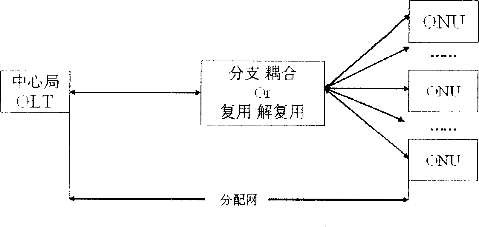
[0050] The core idea of ​​the present invention is to sample and detect the electrical signal after photoelectric conversion, so that the detection of time slot conflict becomes simple and easy, and the cost is reduced, effectively overcoming the problems existing in the prior art.

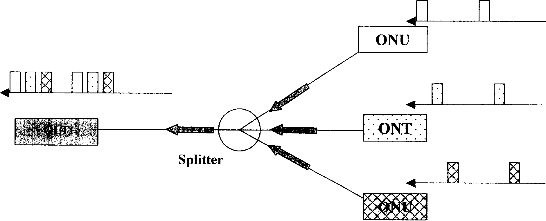
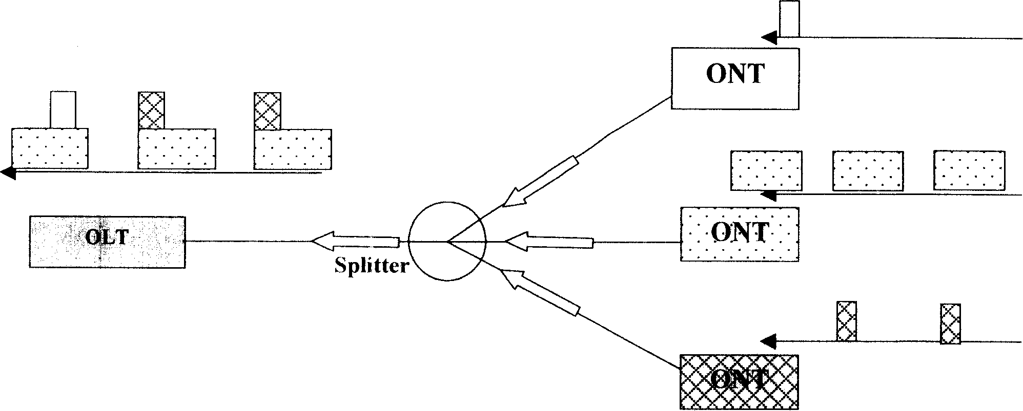
[0051] When the ONTs transmit normally, there is a certain guard time between the transmission time slots of different ONTs; when the upstream time slots conflict, the optical signals of different ONTs are superimposed, which will cause the optical signals of the superimposed part to increase. Since the electrical signal obtained after the optical signal undergoes photoelectric conversion by the optical transceiver is consistent with the optical signal, when the time slot conflicts, the peak value of the electrical signal will be greater than the peak value under normal conditions due to superposition.

[0052]Therefore, the peak voltage output by the optical receiver in the upstream time slot of t...


PUM


Abstract

The invention relates to a detection method for uplink timeslot confliction in a passive optical network and an optical line terminal thereof. The method mentioned in the invention comprises: A, the optical line terminal (OLT) samples the electrical signal peak of an uplink timeslot; and B, the OLT judges whether the sampled electrical signal peak exceeds the normal electrical signal peak of the uplink timeslot, if it is, determines that the timeslot confliction occurs in the uplink timeslot, otherwise determines that the uplink timeslot is normal. The inventive optical line terminal comprises an optical transmitter, an optical receiver and a control unit, wherein the optical receiver comprises a detection unit which further comprises a photoelectric conversion unit and an electrical signal detection unit. The invention also relates to a detection device which comprises a peak detection unit, a sampling unit, a comparison unit and a storage unit. The invention can sample and detect the electrical signal after photoelectric conversion, so that the detection of uplink timeslot confliction is simple and easy to operate with low cost.

Description

technical field [0001] The invention relates to the technical field of communication, in particular to a detection method for uplink time slot conflict in a passive optical network and an optical line terminal. Background technique [0002] A passive optical network (PON) is composed of an optical line terminal (OLT) located at the central office (CO) and a series of optical network terminals (ONU / ONT, hereinafter referred to as ONT) located at the customer premises. The optical line terminal (OLT) and the optical network terminal (ONU / ONT) are connected through an optical distribution network (ODN) composed of optical fiber, passive optical splitter or coupler. [0003] like figure 1 , In a PON network, the backbone fiber can be pulled from the central office to the broadband service sub-area or office park, and then a passive optical splitter is used to separate several branch fibers from the backbone fiber to each building or business equipment. This method enables mult...

Claims


Application Information

Patent Timeline
Patent Type & Authority Applications(China)
IPC IPC(8): H04B10/08H04B10/075
Inventor 周箴黄伟江涛王运涛
Owner HUAWEI TECH CO LTD
Why Eureka
Try Eureka