Current automatic generation control navigation mark lamp

A technology of water flow power generation and beacon light, which is applied in navigation route marking, electric light circuit layout, energy-saving control technology, etc., can solve the problems of theft, easy damage of solar cells, etc., and achieve the effect of long service life

Inactive Publication Date: 2008-04-09
YANCHENG TEACHERS UNIV
View PDF1 Cites 1 Cited by
  • Summary
  • Abstract
  • Description
  • Claims
  • Application Information

AI Technical Summary

Problems solved by technology

[0002] Navigation lights have been used in shipping waterways fo...

Method used


Image

  • Current automatic generation control navigation mark lamp

Examples


Embodiment Construction

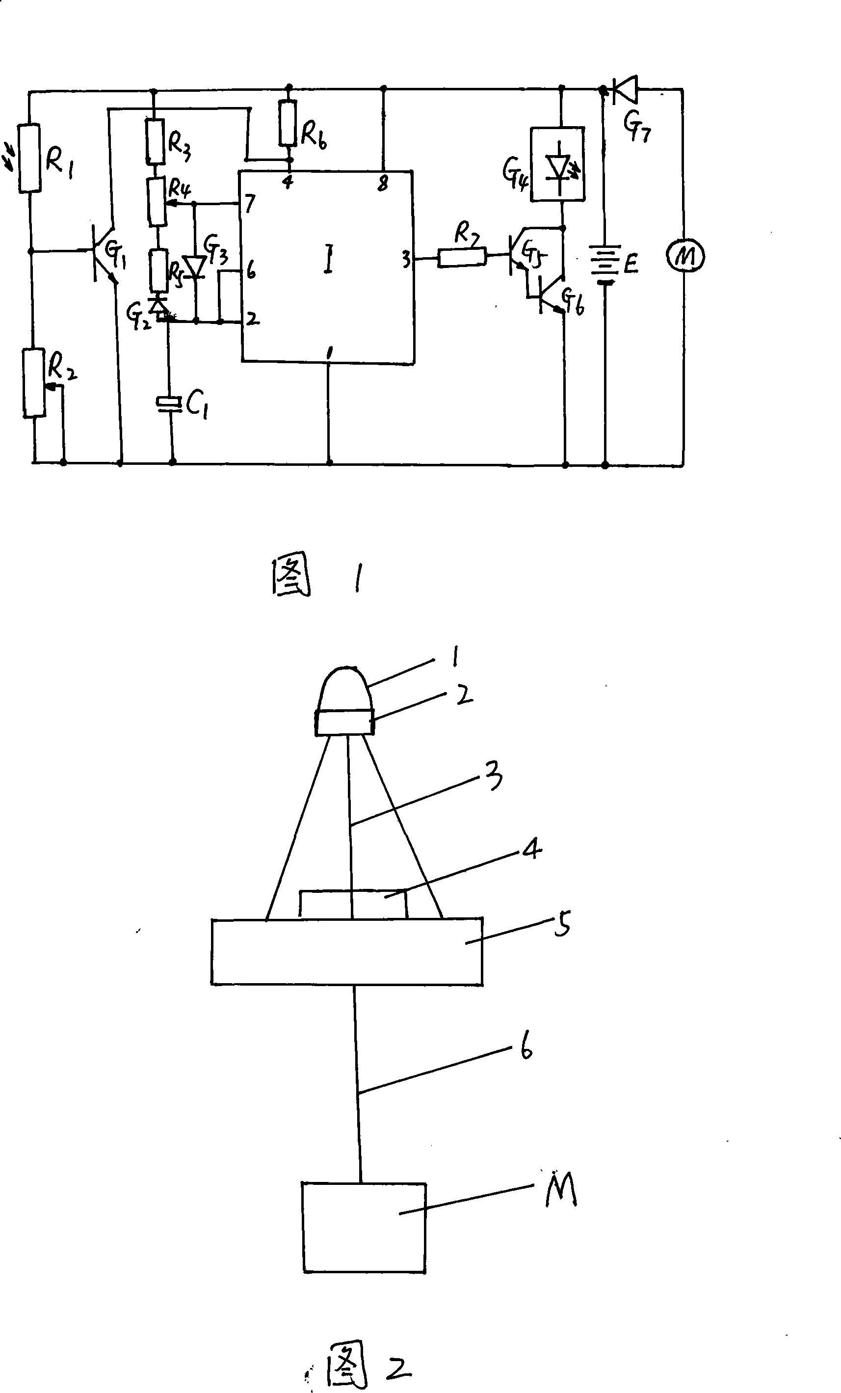
[0010] In Figure 1, the photoresistor (R 1 ) and variable resistor (R 2 ) connected in series to the two terminals of the battery (E), the triode (G 1 ) base and photoresistor (R 1 ) connected, the triode (G 1 ) The emitter is connected to the negative pole of the battery (E), and the triode (G 1 ) collector is connected to 555 integrated circuit (I) 4 pins, 555 integrated circuit (I) 4 pins pass through resistor (R 6 ) is connected to the positive pole of the storage battery (E), the 8 pins of the 555 integrated circuit (I) are connected to the positive pole of the storage battery (E), the 1 pin of the 555 integrated circuit (I) is connected to the negative pole of the storage battery (E), and the 555 integrated circuit (I) is connected to the negative pole of the storage battery (E). Pin 7 is connected to a variable resistor (R 4 ) center tap, 555 integrated circuit (I) 2 pins and 6 pins are connected through a diode (G 3 ) and 555 integrated circuit (I) 7 pins are con...


PUM


Abstract

The invention relates to an automatically controlled lantern by current generation and pertains to the navigational route electric technical field. The circuit consists of a photo resistance, a resistance, a capacitance, a diode, a dynatron, a 555 integrated circuit, a high brightness LED array, a storage battery and a low current generator. The invention is characterized in that: one end of the high brightness LED array is connected with a collector electrode of a composited tube and the other end is connected with an anode of the storage battery; the low current generator in series connection with the diode is connected with both ends of the storage battery; circuit elements are welded on a breadboard and solidified by epoxy resin glue. One end of a center shaft is connected with the lower part of a buoy and the other end is fixed with the low current generator. The adoption of the technical proposal has the advantages and positive effects of current generation and electric energy storage for circuit operation and long service life.

Description

Technical field [0001] The invention relates to an automatic control beacon light for water flow power generation, which belongs to the technical field of shipping waterway electronics. Background technique [0002] Navigation lights have been used in shipping waterways for a long time. Some lights need to be powered on to emit light; steal. Contents of the invention [0003] The purpose of the present invention is to provide an automatic control beacon light for water flow power generation, which uses water flow power generation to store electric energy for circuit operation, and controls high-brightness light-emitting diode arrays to flash and emit light through a circuit composed of a photosensitive resistor and a 555 integrated circuit. [0004] The purpose of the present invention is achieved like this: the circuit is made up of photoresistor, resistance, electric capacity, diode, triode, 555 integrated circuits, high-brightness light-emitting diode array, storage ba...

Claims


Application Information

Patent Timeline
IPC IPC(8): H05B37/02B63B51/00
CPCY02B20/42Y02B20/40
Inventor 周殿凤
Owner YANCHENG TEACHERS UNIV
Why Eureka
Try Eureka