
Optical fibre bundle processing method

An optical fiber, fiber technology, applied in the direction of bundle optical fiber, optics, cladding fiber, etc., can solve the problems of signal and pump loss, extremely sensitive to interference, and the size of the signal fiber core, to avoid mechanical and optical characteristics. The effect of changes in

Active Publication Date: 2008-04-09
LIEKKI OY
View PDF13 Cites 5 Cited by
  • Summary
  • Abstract
  • Description
  • Claims
  • Application Information

AI Technical Summary

Problems solved by technology

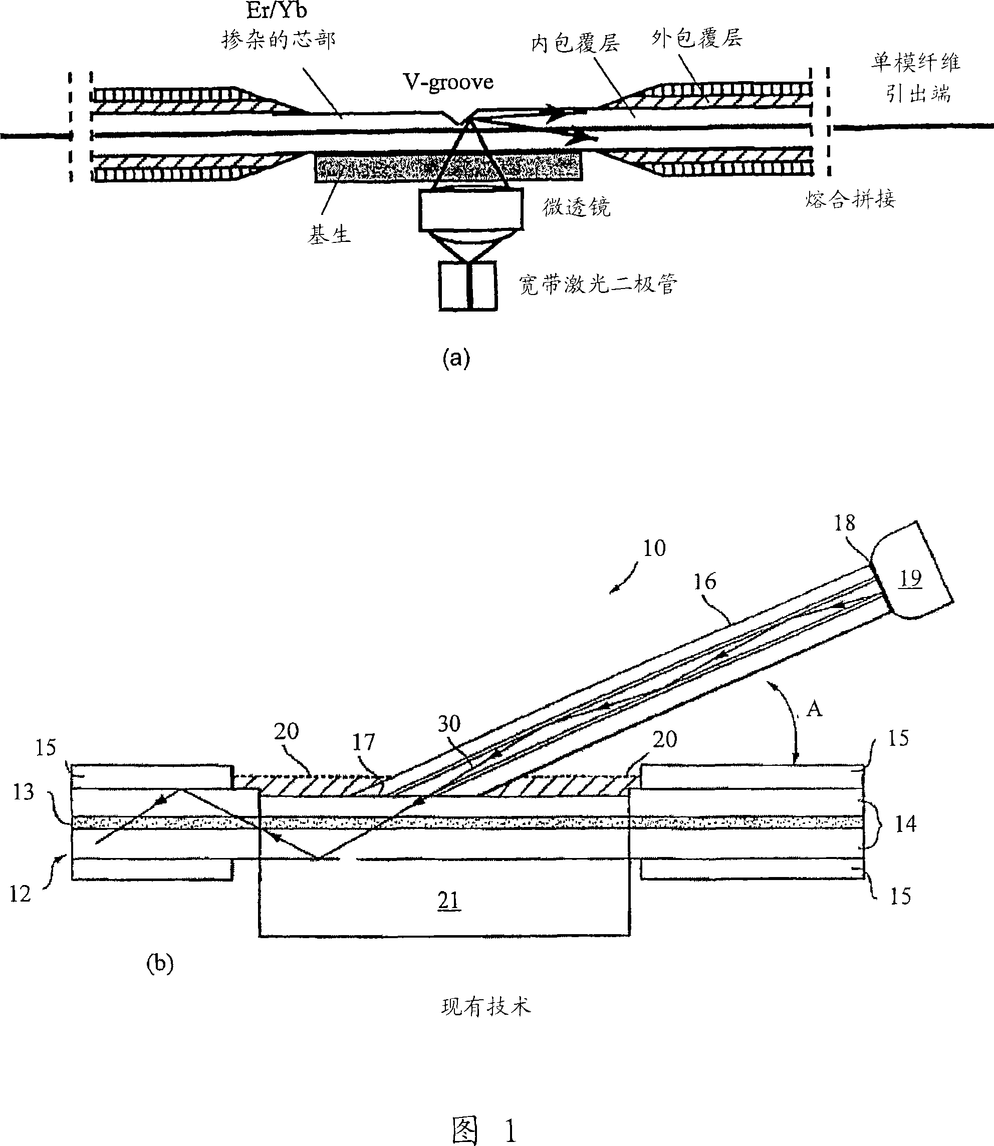
Both of these methods reduce the risk of any gaps or discontinuities between the fused fibers, but still leave the problem of careful control of the fused fibers and, most importantly, the size of the core of the signal fiber when the fibers are tensioned. Variety
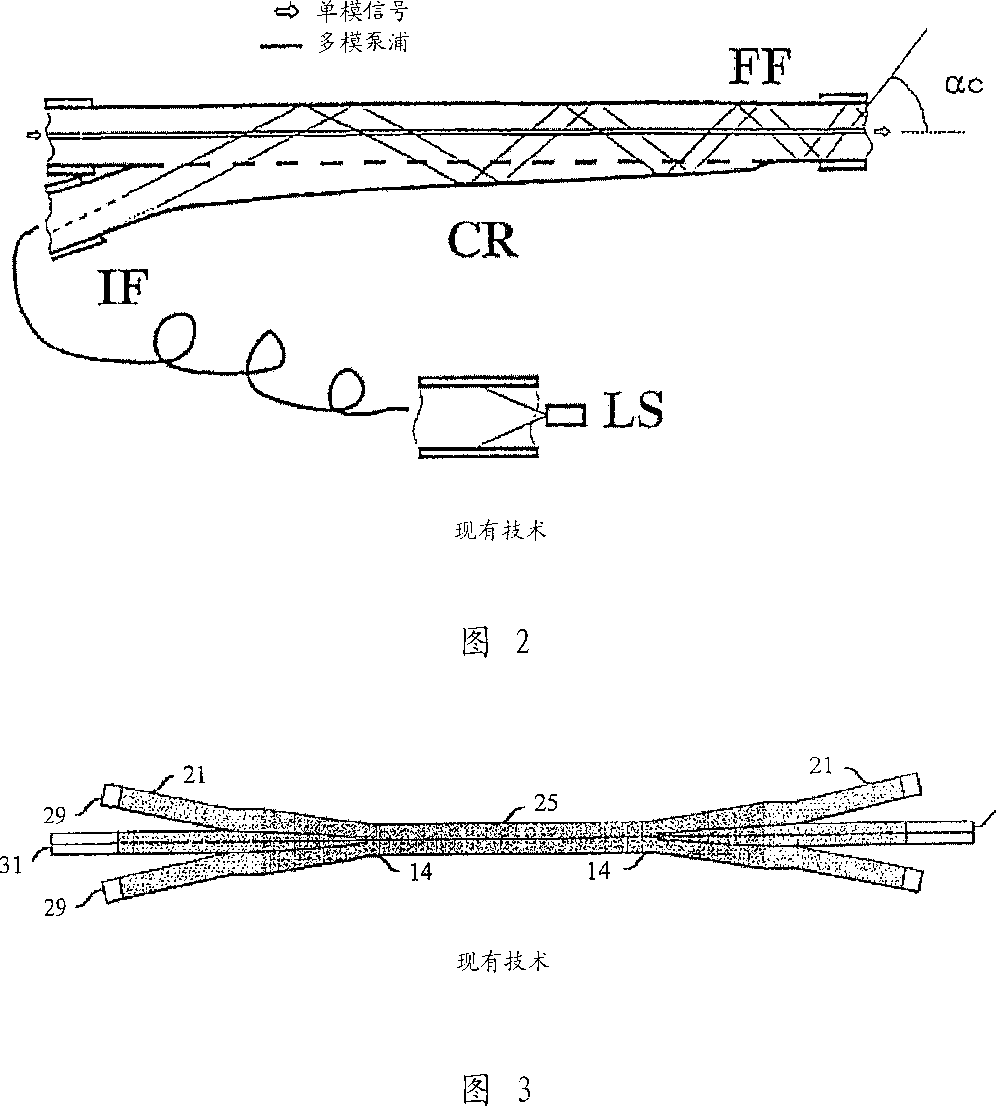
Unfortunately, this coupler is still manufactured separately and is extremely sensitive to any disturbance in the fusion process that can excite higher order modes and cause additional signal and pump losses
Therefore, the use of such couplers in high-power fiber laser / amplifiers based on large-mode-area fibers introduces additional difficulties in maintaining beam quality close to the single-mode characteristic

Method used


Image

  • Optical fibre bundle processing method
  • Optical fibre bundle processing method
  • Optical fibre bundle processing method

Examples


example 1

[0088] In one embodiment of the present invention, a Key Hole fiber structure (cloverleaf fiber) is constructed, FIG. 5 . The fiber structure includes a pump fiber 10 , a capillary 11 with an air hole 12 in the middle, a signal fiber 14 with an active core 13 , and a low modulus polymer coating 15 .

example 2

[0090] In the second example, a keyhole structure type 2 is established, FIG. 6 . The fiber structure includes a pump fiber 10 , a capillary 11 with an air hole 12 in the middle, a signal fiber 14 with an active core 13 , and a low modulus polymer coating 15 .

example 3

[0091] Example 3, fiber with forced bending direction

[0092] The synthetic fibers of the present invention allow many different configurations with respect to their size, shape, number and position of each of their elements. Some of these configurations can be used to improve the properties of fiber lasers or amplifiers made from these fibers. For example, it is clear that the fiber geometry in Figure 7 makes the fiber very hard to bend in one direction, but very easy to bend in the perpendicular direction. This property can be used where the bending direction of the fiber is important to control the modal properties of the active fiber. Thus, the active fiber geometry and orientation with respect to other elements can be fixed during the preform fabrication stage, and the spatial relationship remains constant during fiber drawing and thereafter. This property of the fibers of the present invention is of paramount importance, especially in the case of multimode large mode ...


PUM


Abstract

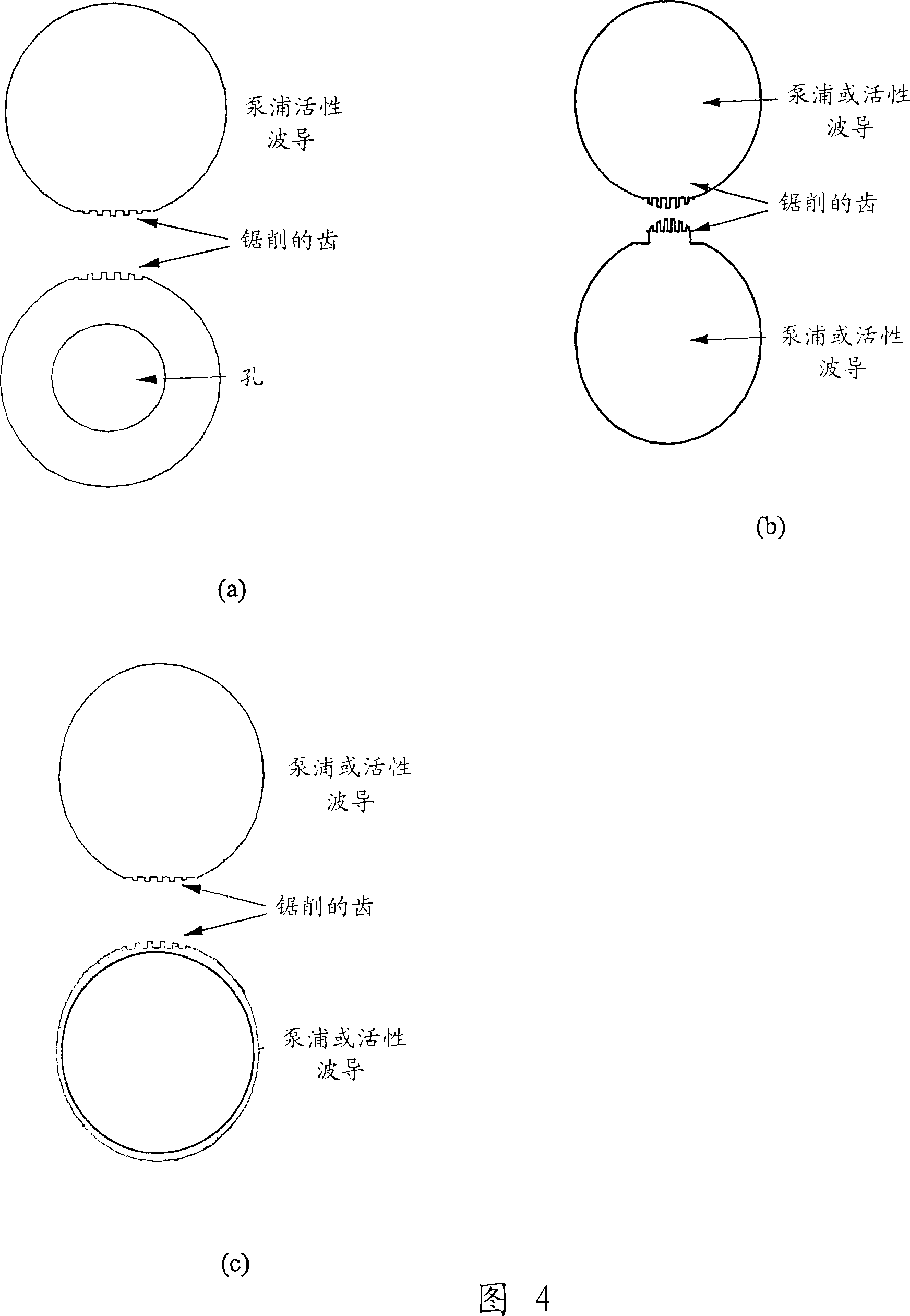
The invention relates to a process of preparing an optical fiber joint, wherein an optical fiber or its undrawn precursor is brought into contact with a longitudinal element and attached to it via a ridge-groove fitting prior to drawing of the final optical fiber joint. The longitudinal element can be another optical fiber or its precursor or a removable and / or workable bridging element.

Description

technical field [0001] The present invention relates to a process for preparing an optical fiber splice, and to a process for preparing an optical fiber bundle containing an optical fiber using the fiber splicing process. Clusters containing optical devices are useful in fiber lasers and amplifiers, particularly when coupling light from a multimode pump source to one or more double-clad fibers including active elements located in the fiber core. Background technique [0002] The power output from double-clad fiber lasers has recently increased significantly. In recent experiments, hundreds of watts of power have been achieved from essentially single-mode devices, making fiber lasers a serious competitor to, for example, lamp and diode-pumped (ND: glass) Nd:YAG in the field of materials processing. In addition to continuous wave operation, pulsed operation and pulsed amplification down to the femtosecond range with peak powers well in excess of 100 kW have also been demonstr...

Claims


Application Information

Patent Timeline
Patent Type & Authority Applications(China)
IPC IPC(8): G02B6/04H01S3/094G02BG02B6/032G02B6/036G02B6/28G02B6/42H01S3/067H01S3/0941
CPCH01S3/094007G02B6/03622H01S3/094053H01S3/0941G02B6/2835G02B6/4214H01S3/06729H01S3/094057G02B6/2852G02B6/032H01S3/06708G02B6/2821
Inventor 西莫·塔梅拉卡勒·拉-加科
Owner LIEKKI OY
Learn More