Hot compress pad

A hot compress and heat technology, applied in the shape of heating elements, heating appliances for therapeutic treatment, cooling appliances for therapeutic treatment, etc., can solve the problems of complex overall structure and increased cost, and achieve the reduction of material and processing costs and power saving energy effect

Active Publication Date: 2008-04-16
共青城航群电子有限公司
View PDF1 Cites 2 Cited by
  • Summary
  • Abstract
  • Description
  • Claims
  • Application Information

AI Technical Summary

Problems solved by technology

However, the electric heating wire and multiple ceramic heat conducting blocks of the second heat pad structure are accommodated in each heat conduction space, and the heat generated by the electric heating wire must be conducted to the ceramic heat conduction block through the aluminum foil surface layer; and each heat conduction space is in Composed of the combination of woven fabric strips and aluminum foil surface layer, the overall structure is quite complicated, which will increase the cost of materials and processing

Method used


Image

  • Hot compress pad
  • Hot compress pad
  • Hot compress pad

Examples


Embodiment Construction

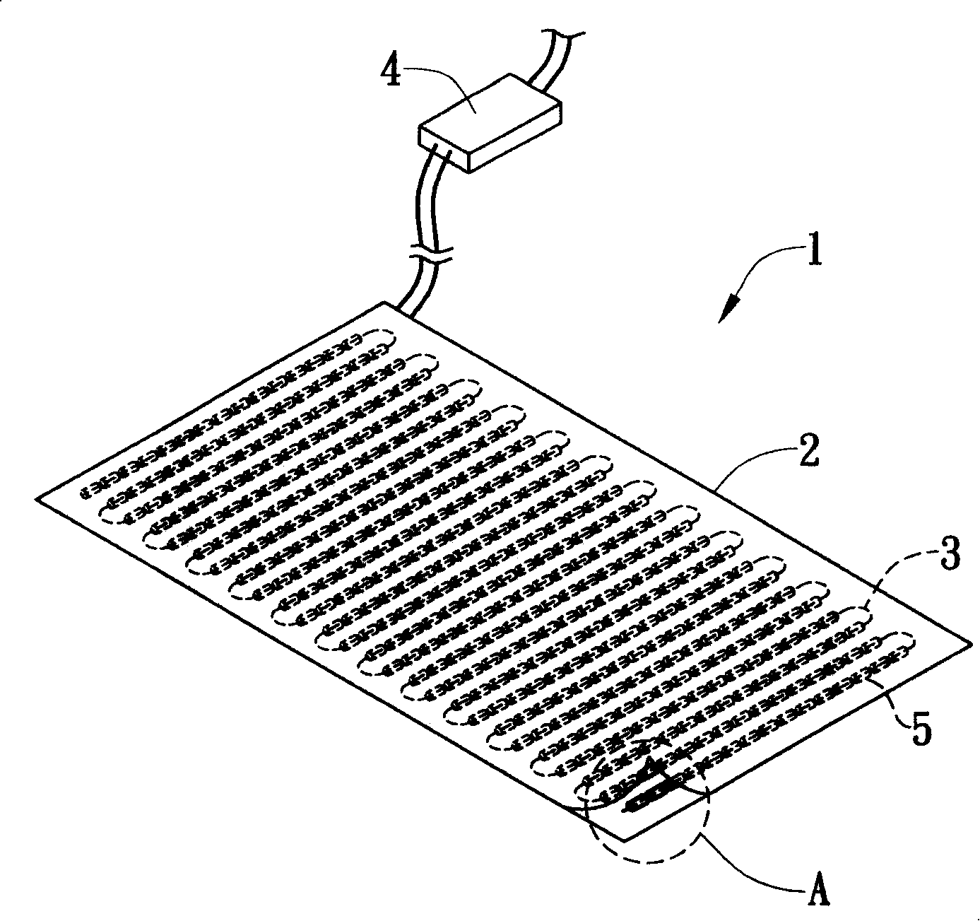
[0024] see figure 1 , figure 2 As shown, it is a preferred embodiment of the heating pad 1 of the present invention, including a bag body 2 , a heating wire 3 , a controller 4 and a plurality of heat preservation components 5 .

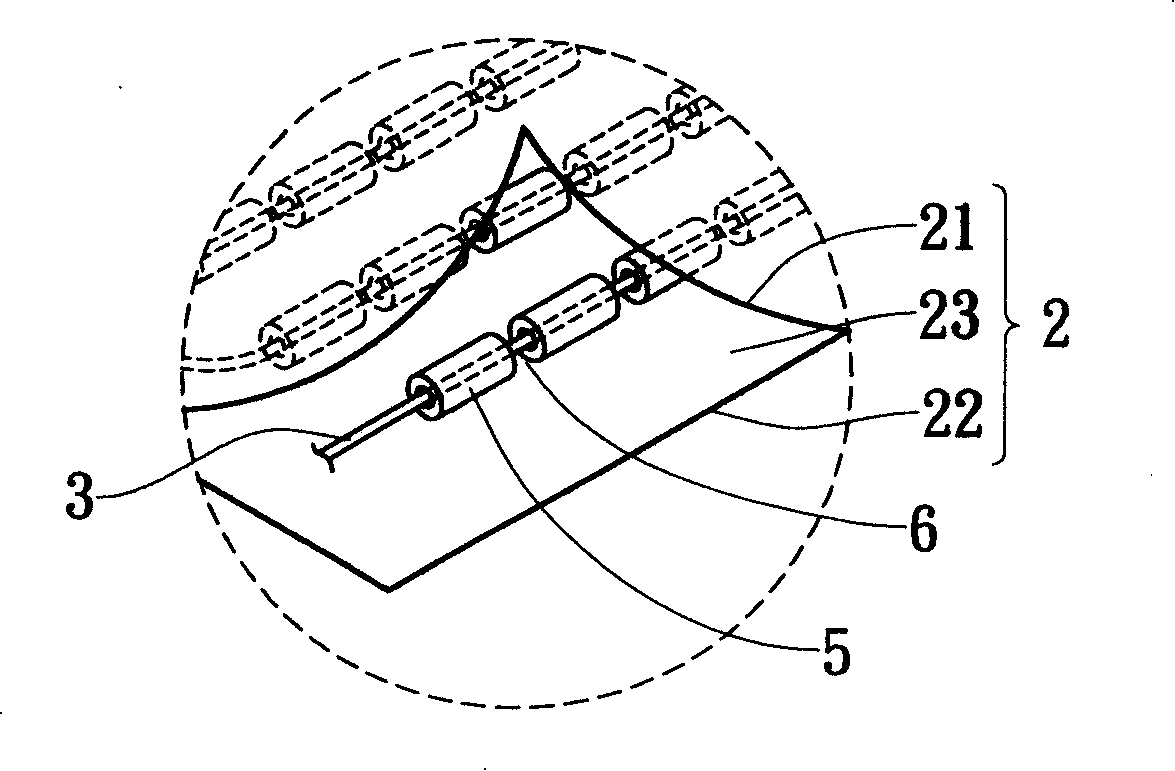
[0025] The bag body 2 is formed by stacking a surface layer 21 and a bottom layer 22 up and down to form an accommodating space 23 inside the bag body 2 . The heating wire 3 is accommodated in the bag body 2 and combined in the accommodating space 23 sandwiched between the surface layer 21 and the bottom layer 22 in a manner of continuous bending on the same plane. One end of the heating wire 3 is connected to a power supply, and the other end is grounded, and a controller 4 is connected between the heating wire 3 and the power supply. During implementation, a trigger circuit, a temperature feedback circuit and a microprocessor connected to each other are provided in the controller 4, and the trigger circuit is connected with the heating wire 3, s...


PUM


Abstract

A fomenting pad is in a bag arranged with a heating wire, and with a plurality of thermal insulating components coupling on the heat wire. While electrifying, a controller controls the heating temperature of the heating wire, so as to supplying human body to foment, during fomenting course, the thermal insulating components absorb the partial heat generated by the heat wire, so as to continuously radiating heat by the thermal insulating components and prolong the fomenting time after electric broken and the heating wire stops heating. When carrying out, the thermal insulating components can radiate far infrared ceramic pipe, so during fomenting course, radiate far infrared at the same time, to achieve human body health effect.

Description

technical field [0001] The present invention relates to a heat compressing device, in particular to a heat compress pad which can absorb part of the heat generated by the heat generating wire and keep it warm to prolong the effect of heat compress by inserting a plurality of ceramic tubes on the outside of a heating wire. Background technique [0002] see image 3 As shown, it is a very common heat pad structure on the market at present. It mainly installs a set of upper and lower conductive plates a1 in a bag, and a plurality of ceramic resistors a2 are sandwiched between the two conductive plates a1. The outer surfaces of the two conductive plates a1 and the ceramic resistors a2 are then coated with a soft heat-resistant insulating colloid a3 to form a thermal compress a. When energized, the second conductive plate a1 can generate temperature to achieve the effect of hot compress on the human body, while the ceramic resistor a2 can increase the internal resistance when the...

Claims


Application Information

Patent Timeline
Patent Type & Authority Applications(China)
IPC IPC(8): A61F7/00A61F7/08H05B3/56
Inventor 廖广埔
Owner 共青城航群电子有限公司
Why Eureka
Try Eureka