Flexible connecting line structure between integrated circuit board in the finger of robot delicacy hand
A technology of integrated circuit boards and circuit boards, which is applied in the direction of cable layout between relative moving parts, manipulators, cable installation, etc., and can solve problems such as poor adaptability of rotating joints, unreasonable layout of circuit boards, and unreasonable wiring methods , to achieve the effect of reasonable routing, avoiding signal interference, and good adaptability
- Summary
- Abstract
- Description
- Claims
- Application Information
AI Technical Summary
Problems solved by technology
Method used
Image
Examples
specific Embodiment approach 1
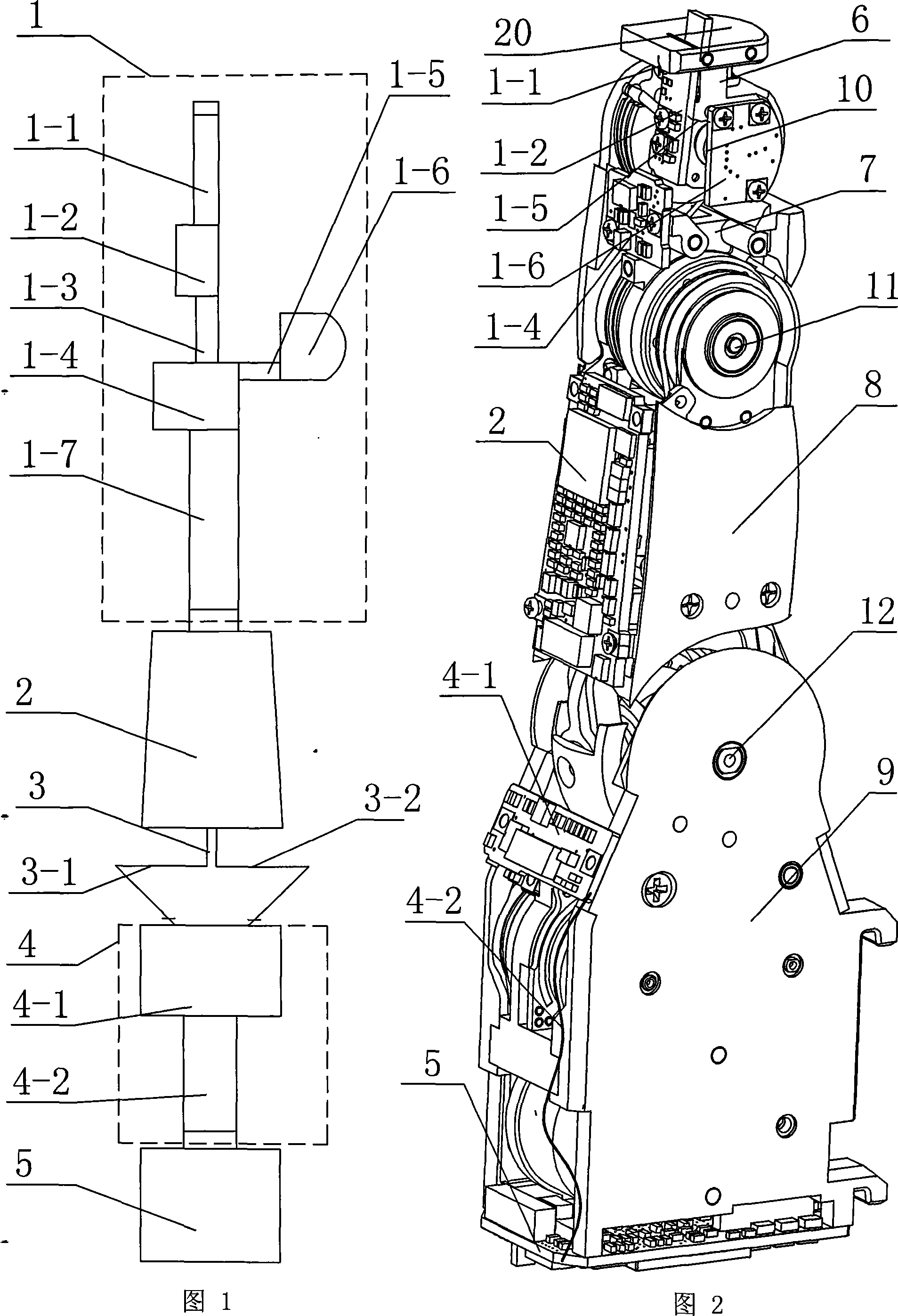
[0008] Embodiment 1: As shown in Figures 1 to 9, the flexible connection structure between the integrated circuit boards in the fingers of the robotic dexterous hand in this embodiment consists of a finger flexible circuit board 1, a finger rigid circuit board 2, and a base joint flexible connection harness 3. The base joint flexible circuit board 4 and the base joint rigid circuit board 5 are composed; the finger flexible circuit board 1 is composed of a first rigid board 1-2, a second rigid board 1-4, a third rigid board 1-6, The first flexible cable 1-1, the second flexible cable 1-3, the third flexible cable 1-5, and the fourth flexible cable 1-7, the first rigid plate 1-2 is fixed on the terminal knuckle 6 Above, the second rigid board 1-4 and the third rigid board 1-6 are respectively fixed on the second knuckle 7 and are perpendicular to each other, one end of the first flexible cable 1-1 is connected to the fingertip torque sensor 20, the first The other end of the fle...
specific Embodiment approach 2
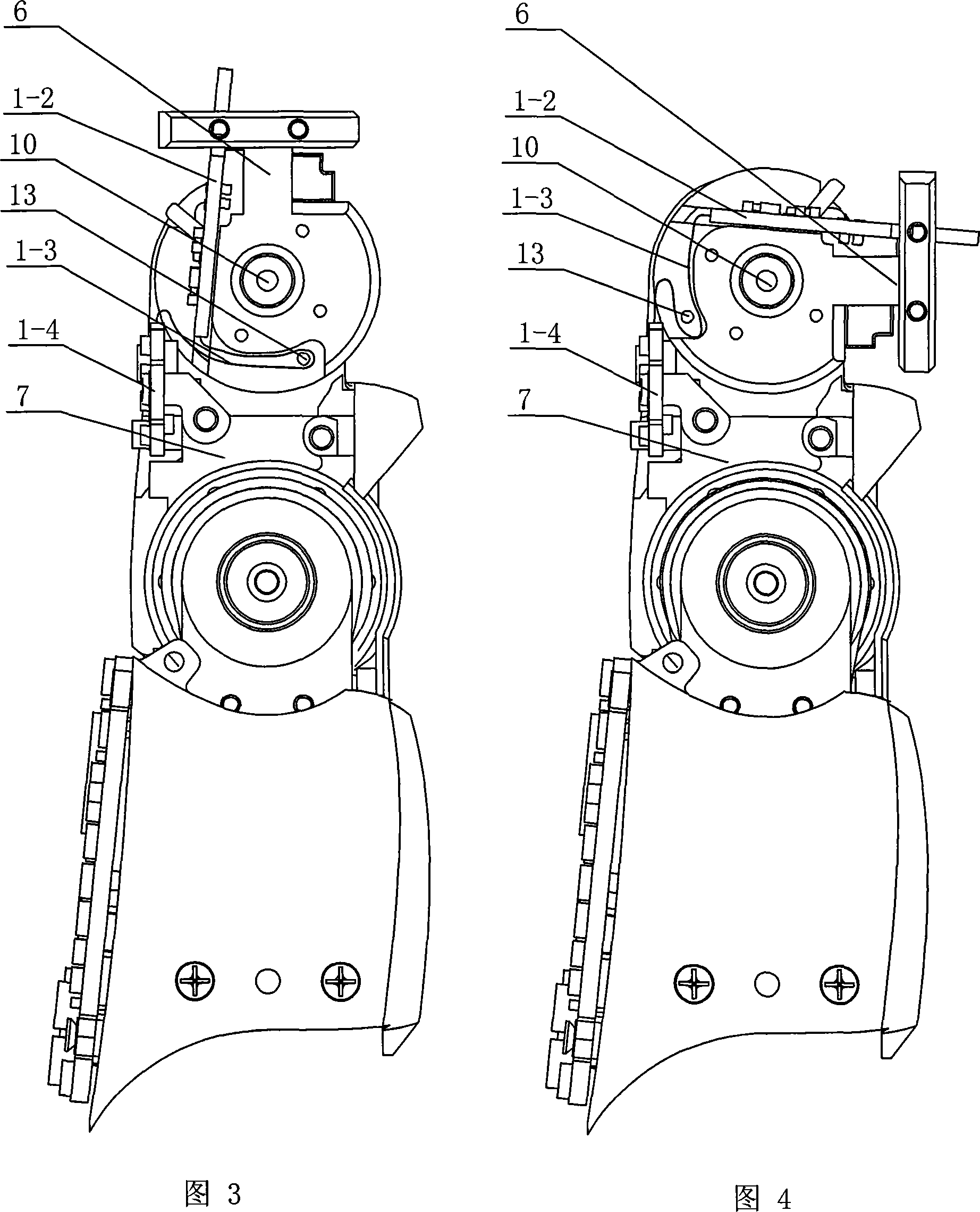
[0009] Specific embodiment two: as shown in Figure 3 and Figure 4, this embodiment also includes a wire pin 13, the wire pin 13 is arranged on the terminal knuckle 6, and the second flexible cable 1-3 is wound on On the said wire pin 13. When the finger end joints are straightened, the distance between the first rigid plate 1-2 and the second rigid plate 1-4 is the smallest, and the excessively long second flexible cable 1-3 is affected by the guide pin 13 and its own rigidity down, folded on the inner side of the second knuckle 7; when the end joint 10 gradually bends, the distance between the first rigid board 1-2 and the second rigid board 1-4 increases, and the second flexible cable 1 is pulled -3, at the same time, the wire pin 13 rotates clockwise around the end joint 10, and the second flexible cable 1-3 can meet the requirement of increasing the distance between the two rigid plates. The function of the wire pin 13 is mainly to pull up the second flexible cable 1-3 wh...
specific Embodiment approach 3
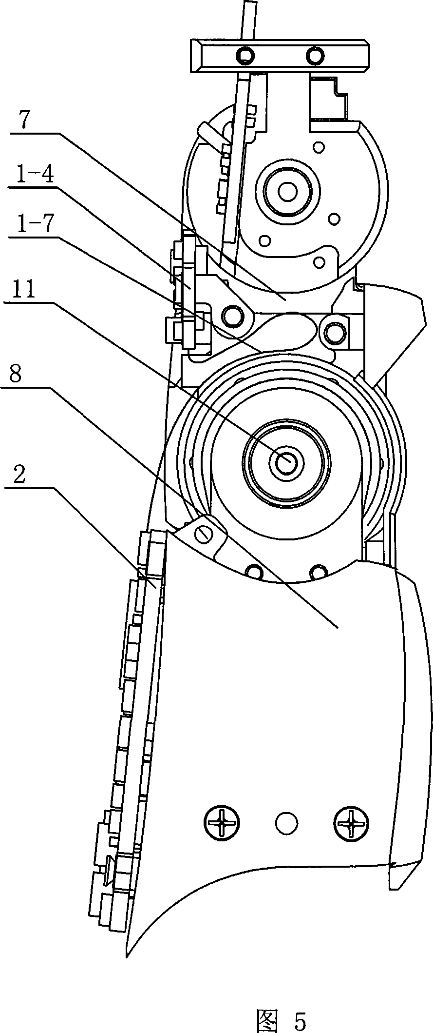
[0010] Embodiment 3: As shown in FIG. 5 and FIG. 6 , the fourth flexible cable 1-7 in this embodiment "straddles" the middle joint 11 , the second rigid board 1-4 and the finger rigid circuit board 2 . When the middle joint 11 is straightened, the distance between the second rigid board 1-4 and the finger rigid circuit board 2 is the smallest, and the excessively long fourth flexible cable 1-7 winds around the middle joint 11 under the action of its own stiffness the outer edge of the second knuckle 7; when the second knuckle 7 of the finger is gradually bent, the distance between the two rigid plates increases, pulling the fourth flexible cable 1-7, the fourth flexible cable 1 -7 can meet the requirement of increased rigid board distance. Other compositions and connections are the same as in the first embodiment.
PUM
 Abstract
Description
Claims
Application Information
 - R&D
- Intellectual Property
- Life Sciences
- Materials
- Tech Scout
- Unparalleled Data Quality
- Higher Quality Content
- 60% Fewer Hallucinations
Browse by: Latest US Patents, China's latest patents, Technical Efficacy Thesaurus, Application Domain, Technology Topic, Popular Technical Reports.
© 2025 PatSnap. All rights reserved.Legal|Privacy policy|Modern Slavery Act Transparency Statement|Sitemap|About US| Contact US: help@patsnap.com


