Coal mine tunnel initating machine

A coal mine roadway and power transmission mechanism technology, applied in the direction of cutting machinery, slitting machinery, driving devices, etc., can solve the problems of not being able to adapt to roadway transportation and transfer of working faces, inconvenient disassembly and reorganization, and large material consumption, so as to save manpower , compact structure and low material consumption

Inactive Publication Date: 2008-04-16
牛保敏
View PDF0 Cites 8 Cited by
  • Summary
  • Abstract
  • Description
  • Claims
  • Application Information

AI Technical Summary

Problems solved by technology

[0002] The traditional methods of excavating coal mine roadways are drilling, blasting, manual coal digging or rock raking machine raking coal, which is labor-intensive, time-consuming, labor-intensive, consumes a lot of materials, and the excavation speed is slow. Accidents such as gas outburst
[0003] At present, some large coal mines use special roadway excavation equipment to replace manual coal mining, but these roadway excavation equipment are bulky and require a lot of accommodation space and work space, which is not suitable for small and medium-sized coal mines with narrow roadways. In addition, the structure is complicated and it is not easy to disassemble. Reorganization, unable to meet the needs of roadway transportation and transfer face
For mines with unstable coal seams, in order to avoid landslide accidents, the roadways cannot be excavated very spaciously. Therefore, these existing large-scale excavation equipment cannot be used in mine roadway construction with unstable coal seams.

Method used


Image

  • Coal mine tunnel initating machine
  • Coal mine tunnel initating machine
  • Coal mine tunnel initating machine

Examples


Embodiment Construction

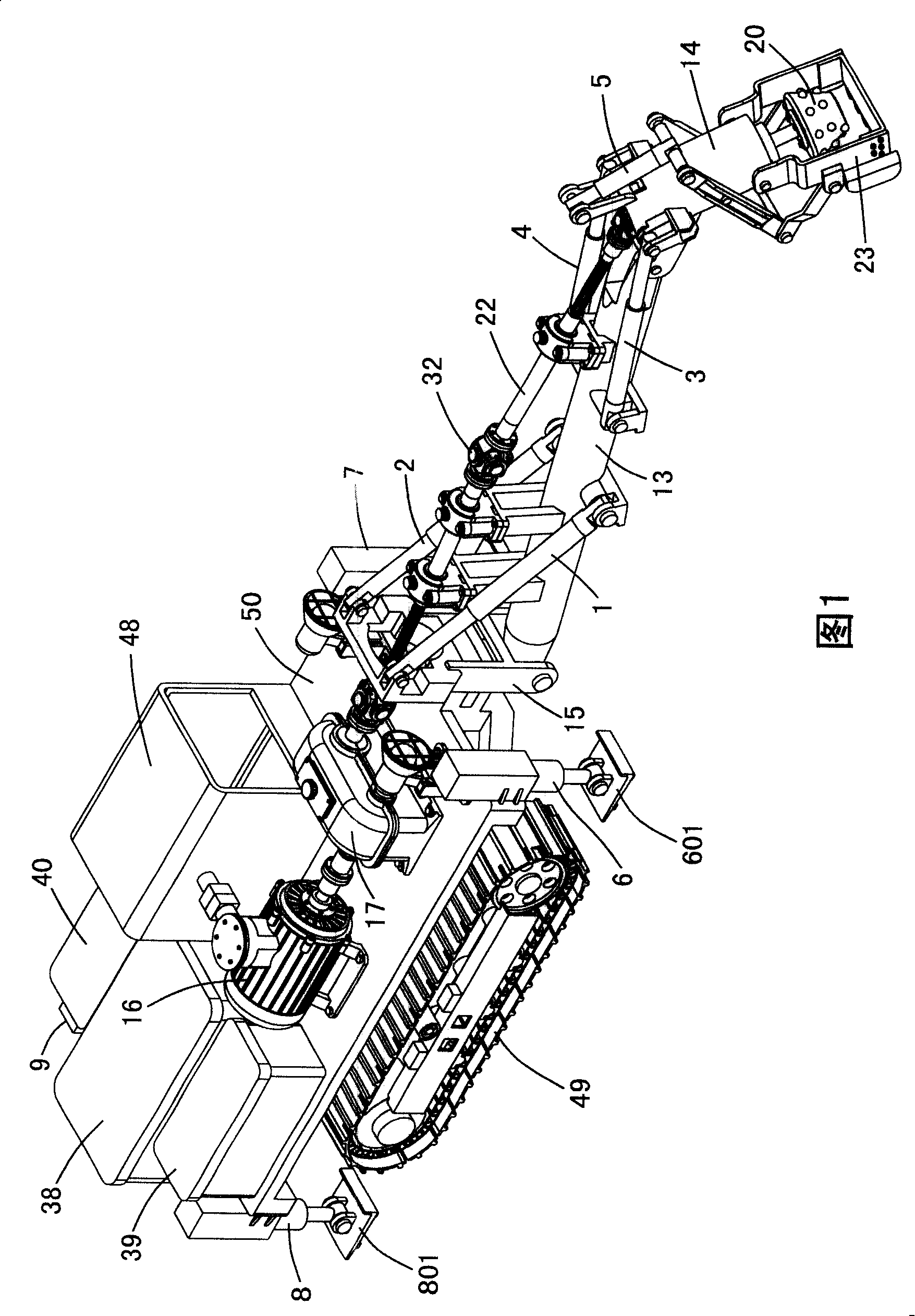
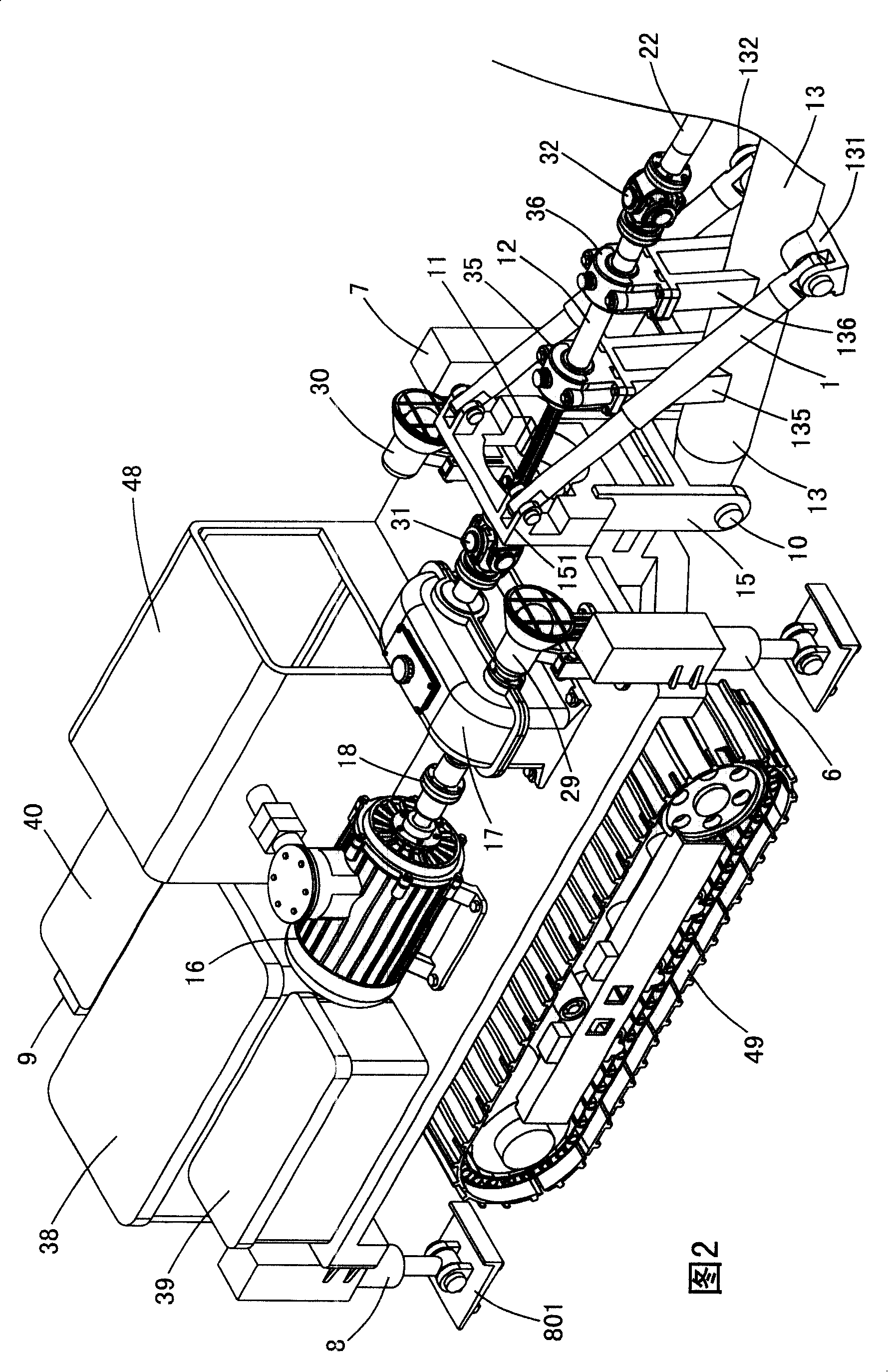
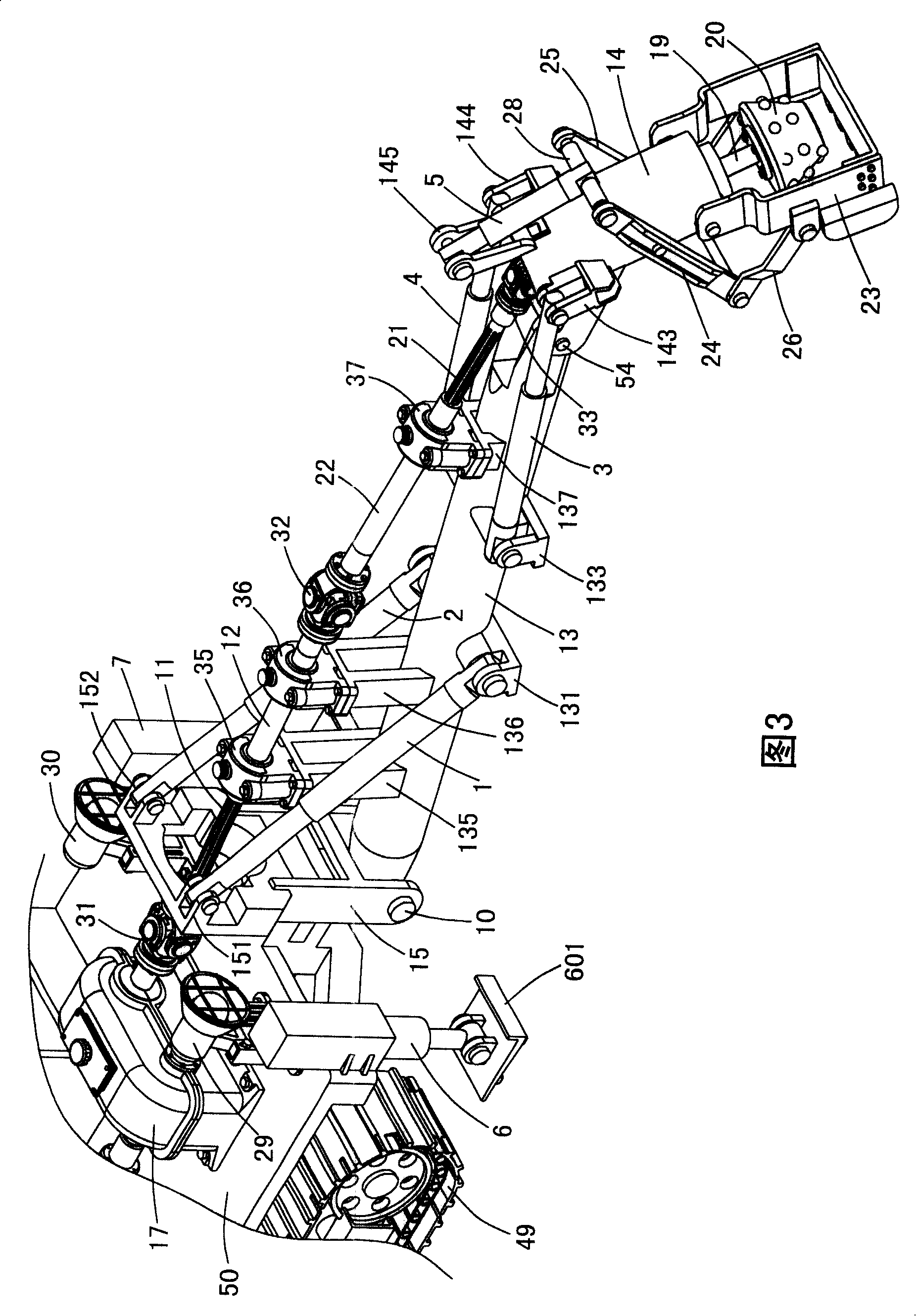
[0038] Labels in the figure:

[0039] 1. The first hydraulic cylinder 2. The second hydraulic cylinder 3. The third hydraulic cylinder

[0040] 4. Fourth hydraulic cylinder 5. Fifth hydraulic cylinder

[0041] 6. Sixth hydraulic cylinder 601. Leg 7. Seventh hydraulic cylinder 701. Leg

[0042] 8. Eighth hydraulic cylinder 801. Leg 9. Ninth hydraulic cylinder 901. Leg

[0043] 10. Shaft 11. First guide shaft 12. First guide sleeve

[0044] 13. Boom 131. Shaft seat 132. Shaft seat

[0045] 135. Support platform 136. Support platform 137. Support platform

[0046] 14. Small arm 143. Shaft seat 144. Shaft seat 145. Shaft seat

[0047] 15. Bracket 151. Shaft seat 152. Shaft seat

[0048] 16. Explosion-proof motor 17. Reducer 18. Flange coupling

[0049] 19. Transmission shaft 191. Bearing 192. Connecting flange

[0050] 20. Crushing head 21. Second guide shaft 22. Second guide bushing

[0051] 23. Rake bucket 231. Rake shovel 232. Guard plate 233. Guard plate

[0052] 24....


PUM


Abstract

The invention discloses an excavator of laneways in a coal mine. The excavator is provided with a large arm and a small arm, wherein, the tail end of the large arm is hinged with the bottom end of a bracket; the rear part of the large arm is provided with a first hydraulic cylinder and a second hydraulic cylinder which are used for controlling the pitch of the large arm; the front part of the large arm is provided with a third hydraulic cylinder and a fourth hydraulic cylinder which are used for pushing and pulling the small arm to move up and down; a drive device consists of an explosion-proof motor and a reducer; a first guide shaft is connected with the output end of the reducer through a first universal coupling; a first guide shaft housing is connected with a second guide shaft housing through a second universal coupling; a second guide shaft is connected with a third universal coupling which is connected with a fourth universal coupling; the fourth universal coupling is connected with the upper end of a transmission shaft arranged in an inner cavity of the small arm; the lower end of the transmission shaft is fixed with a crush head. The invention integrates breaking and coal raking, and is specially used for the excavation of laneways of the coal mine; the invention can also be used in the coal mines with complex geological conditions or unstable coal layers.

Description

technical field [0001] The present invention relates to excavation equipment used in coal mines. Background technique [0002] The traditional methods of excavating coal mine roadways are drilling, blasting, manual coal digging or rock raking machine raking coal, which is labor-intensive, time-consuming, labor-intensive, consumes a lot of materials, and the excavation speed is slow. Gas outburst and other accidents. [0003] At present, some large coal mines use special roadway excavation equipment to replace manual coal mining, but these roadway excavation equipment are bulky and require a lot of accommodation space and work space, which is not suitable for small and medium-sized coal mines with narrow roadways. In addition, the structure is complicated and it is not easy to disassemble. Reorganization cannot meet the needs of roadway transportation and transfer face. For mines with unstable coal seams, in order to avoid the occurrence of landslide accidents, the roadways...

Claims


Application Information

Patent Timeline
Patent Type & Authority Applications(China)
IPC IPC(8): E21C25/06E21C31/02E21C35/00
Inventor 牛保敏
Owner 牛保敏
Why Eureka
Try Eureka