Adjustable safety relief valve

An adjustable pressure relief valve technology, which is applied in the field of auto parts, can solve the problems of unable to set the unloading pressure value and fixed structure, and achieve the effect of easy locking, convenient adjustment and simple adjustment structure

Inactive Publication Date: 2008-04-16
JIANGSU GANGYANG STEERING SYST
View PDF0 Cites 8 Cited by
  • Summary
  • Abstract
  • Description
  • Claims
  • Application Information

AI Technical Summary

Problems solved by technology

However, the structure of the safety valve is fixed, and the unloading pressure value cannot be set by itself according to the working conditions. This structure has certain limitations in the application process.

Method used


Image

  • Adjustable safety relief valve

Examples


Embodiment Construction

[0011] The present invention will be further described below in conjunction with embodiment.

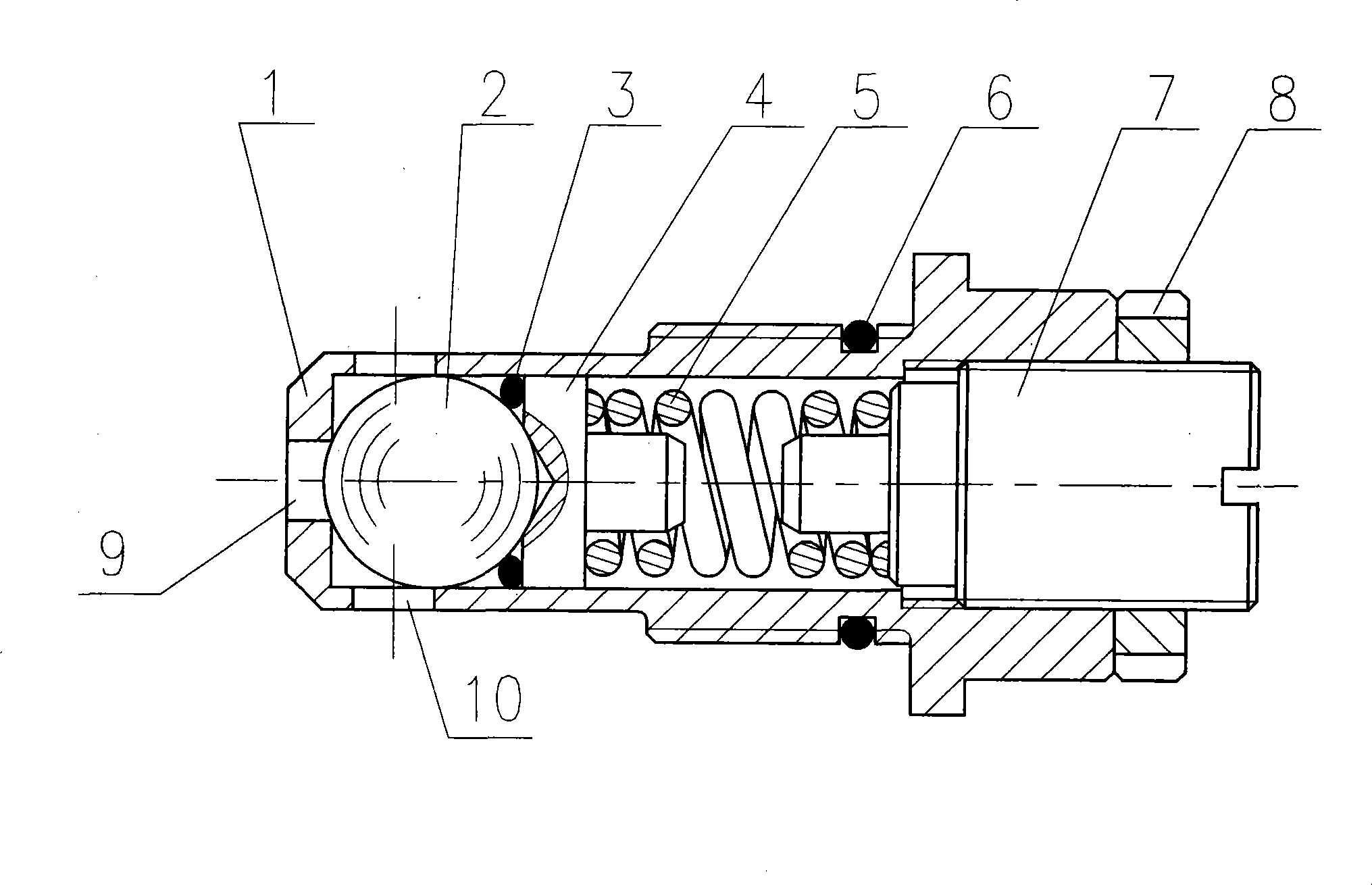
[0012] The adjustable safety pressure relief valve shown in the accompanying drawings includes a valve body 1, a steel ball 2, a sealing ring 3, a slider 4, a spring 5, an O-ring 6, a screw 7 and a nut 8. The valve body 1 is a cylindrical shell member, the middle part of the left end face is provided with a circular oil inlet 9 in the axial direction, and the outer wall of the left end is provided with 2 to 4 radial oil outlets 10. This embodiment is in the GY120 power steering gear. The safety pressure relief valve has a φ4.8mm hole in the oil inlet 9, and two φ3.5mm holes in the oil outlet 10. The inner cavity of valve body 1 is arranged in sequence from left to right with steel ball 2, sealing ring 3, slider 4, and spring 5. Screw 7 is screwed into compression spring 5 from the right end of valve body 1, and is elastically pushed under the elastic force of spring 5. The steel bal...


PUM


Abstract

The invention discloses an adjustable safety relief valve which comprises a valve body, a steel ball, an obturating ring, a sliding block, a spring, an O-shaped obturating ring, a bolt and a nut. The left end surface of the valve body is provided with a round oil inlet, the left outer wall is provided with an oil outlet. The outer wall of the valve body is provided with external threads. The steel ball, the obturating ring, the sliding block and the spring are orderly arranged in the valve body from left to right. An inner hole on right end of the valve body and a bolt form an axial regulation mechanism, and the axial position of the bolt is locked by the nut. The obturating ring is arranged between the matching surface of the sliding block and the steel ball to prevent the oil from axial leaking. The invention can alter the elastic thrust of the spring to the steel ball by adjusting the bolt, namely to regulate the off-load pressure value. The invention is convenient to be adjusted and locked due to the visibility of the adjustable structure and is suitable for safety relief valves of all power steering gears.

Description

technical field [0001] The invention relates to a safety device for controlling oil pressure, in particular to a safety device in a circulating integral hydraulic power steering gear, belonging to the technical field of auto parts. Background technique [0002] The power steering gear is an important part of the steering mechanism of modern automobiles. It realizes steering through hydraulic oil, which greatly reduces the labor intensity of the driver's steering operation. Under normal circumstances, the oil pressure in the power steering gear is the set value, and the steering is flexible and easy to operate under the rated oil pressure. However, when the power steering gear is turned to the limit position, it is as if the load is infinite, causing the oil pressure in the system to rise instantaneously, which may easily cause seal leakage or even damage. In the prior art, a pressure-limiting safety valve is set in the structure to release excessive oil pressure, so as to a...

Claims


Application Information

Patent Timeline
Patent Type & Authority Applications(China)
IPC IPC(8): F16K17/06
Inventor 宋海兵谢军王春宏
Owner JIANGSU GANGYANG STEERING SYST
Why Eureka
Try Eureka