Drying apparatus

一种干燥装置、干燥箱的技术,应用在干燥气体布置、渐进式干燥机、印刷电路干燥等方向,能够解决小开口面积等问题,达到提高干燥效率的效果

Inactive Publication Date: 2008-04-16
KYOWA KAKO KABUSHIKI KAISHA
View PDF2 Cites 4 Cited by
  • Summary
  • Abstract
  • Description
  • Claims
  • Application Information

AI Technical Summary

Problems solved by technology

In addition, the drying box has no openings communicating with the outside air except for its inlet and outlet, which also have only a small opening area.

Method used


Image

  • Drying apparatus
  • Drying apparatus
  • Drying apparatus

Examples


Embodiment Construction

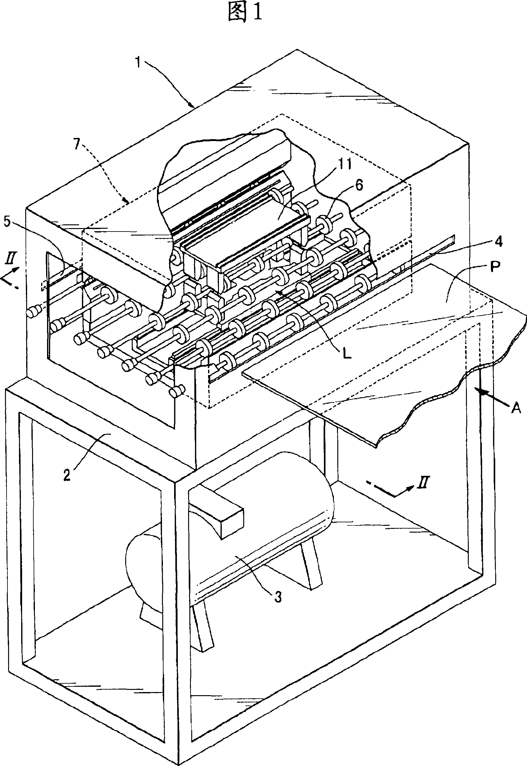
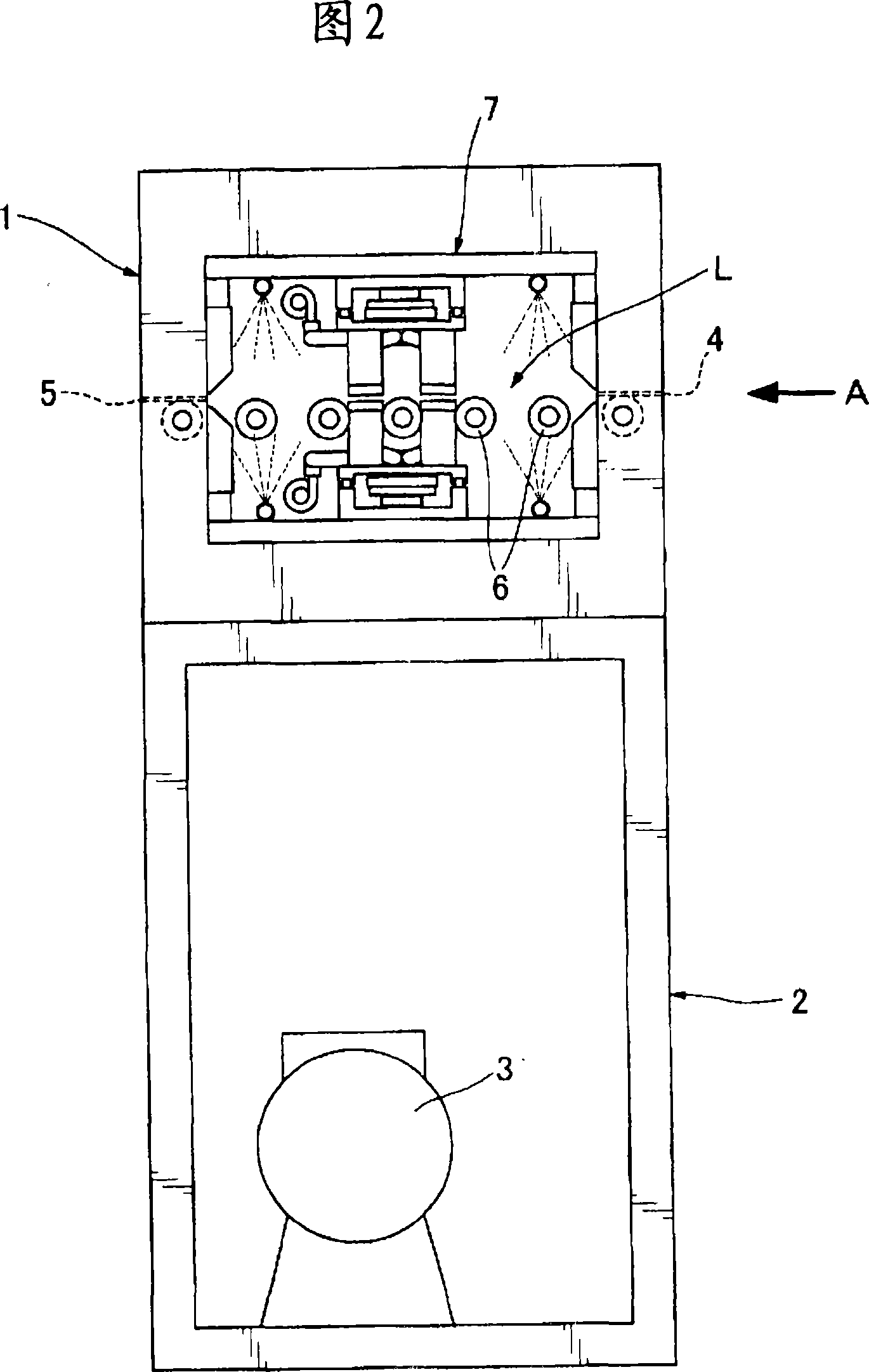
[0053] Next, referring to the drawings, a description will be given of a drying device that dries the object to be cleaned after washing with water. Fig. 1 is a schematic perspective view of a drying device, a part of which is cut off for viewing the inside. Fig. 2 is a II-II view of the drying device in Fig. 1 . In FIGS. 1 and 2 , the main body 1 of the drying device is provided on a stand 2 , and a box 3 for supplying dry air to the main body 1 of the drying device is provided below the stand 2 . The main body 1 of the drying device has an inlet 4 and an outlet 5 for flat objects P to be cleaned, such as a liquid crystal panel or a printed circuit board. A plurality of conveying rollers 6 are arranged between the feeding port 4 and the discharging port 5 . The conveying roller is rotatably attached to a rotary shaft supported by the main body 1 of the drying device, and forms a conveying path L for the object to be cleaned.

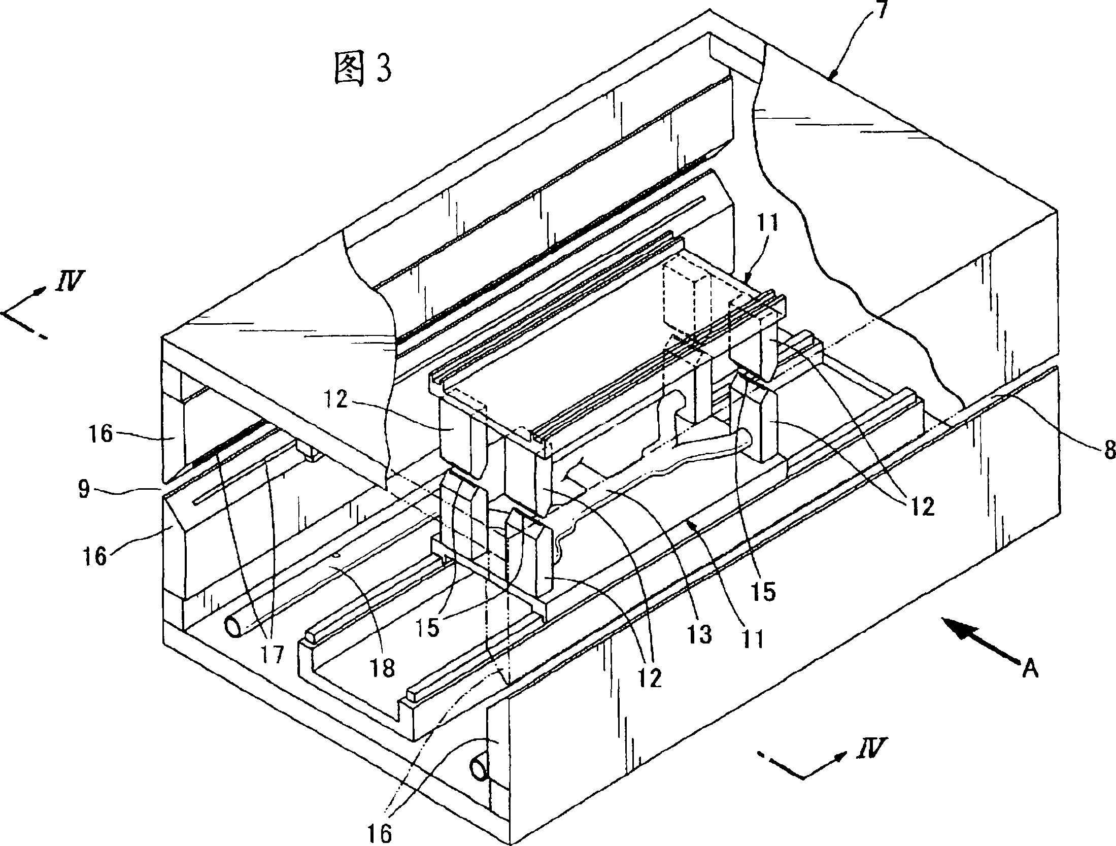
[0054] Inside the drying device main body 1 is...


PUM


Abstract

A drying device has a linear drive device for linearly moving, in a drying box, a spray nozzle in a direction orthogonal to a conveyance direction of an object to be washed, and an ejection opening of the spray nozzle is formed as a slit stretching in the conveyance direction. A pair of nozzles is arranged at an inlet and outlet of the drying device, and each nozzle has a slit extended in the direction orthogonal to the conveyance direction, by the width of the object to be washed. Those surfaces of the nozzles that face each other are each inclined from an inner edge to an outer edge so that the distance between the inner edges of the nozzles is greater than the distance between the outer edges.

Description

technical field [0001] The present invention relates to a drying device, in particular to such a drying device used in the manufacturing process of liquid crystal display devices or semiconductor devices, etc. The object to be cleaned is dried. Background technique [0002] Accurate dehydration and rapid drying after dehydration are required in order to quickly dry the object to be cleaned, such as a liquid crystal panel or a printed circuit board, which has been cleaned with a liquid. In a conventional drying device, a residual liquid removal chamber for dehydration is provided before an ultra-drying chamber for drying objects to be cleaned. In this drying device, the residual liquid removal chamber is provided with an air nozzle inclined toward the delivery port so as to generate an air component flowing in a direction opposite to the direction in which the object to be cleaned is transported. This is for improving cleaning liquid removal efficiency and preventing air fr...

Claims


Application Information

Patent Timeline
Patent Type & Authority Applications(China)
IPC IPC(8): F26B15/12H01L21/304G02F1/13
CPCH05K2203/1509F26B21/004H01L21/67051H05K3/227F26B15/12H01L21/67034F26B13/10H01L21/304G02F1/13
Inventor 竹森利则
Owner KYOWA KAKO KABUSHIKI KAISHA
Why Eureka
Try Eureka