
Method and device for synchronising two bus systems, and arrangement consisting of two bus systems

一种总线系统、设备的技术,应用在时分多路复用系统、传输系统、数字传输系统等方向

Active Publication Date: 2008-04-16
ROBERT BOSCH GMBH
View PDF0 Cites 11 Cited by
  • Summary
  • Abstract
  • Description
  • Claims
  • Application Information

AI Technical Summary

Problems solved by technology

[0008] However, the disadvantage of this known method is that the host controller or the processor is always intervened, so that at least one user processor is heavily loaded during the synchronization of several networks or bus systems and a certain delay for the software occurs. dependency

Method used


Image

  • Method and device for synchronising two bus systems, and arrangement consisting of two bus systems
  • Method and device for synchronising two bus systems, and arrangement consisting of two bus systems
  • Method and device for synchronising two bus systems, and arrangement consisting of two bus systems

Examples


Embodiment Construction

[0028] The invention will now be explained in greater detail below with the aid of examples.

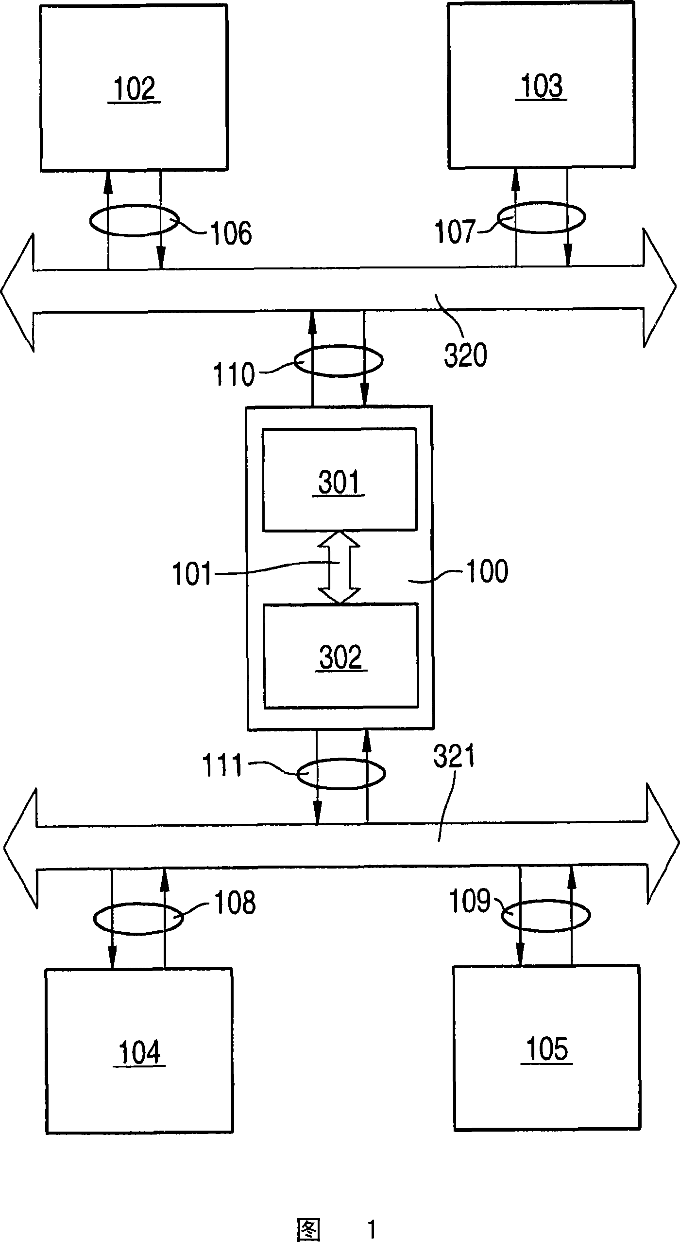
[0029] FIG. 1 shows an arrangement consisting of two bus systems 320 and 321 and a device as a gateway between the bus systems. The bus system 320 here has subscribers or nodes 102 and 103 , which are connected to the bus system via bidirectional connections 106 or 107 . Also shown is a second bus system 321 which has subscribers 104 and 105 and is connected to these subscribers via bidirectional interfaces 108 and 109 .

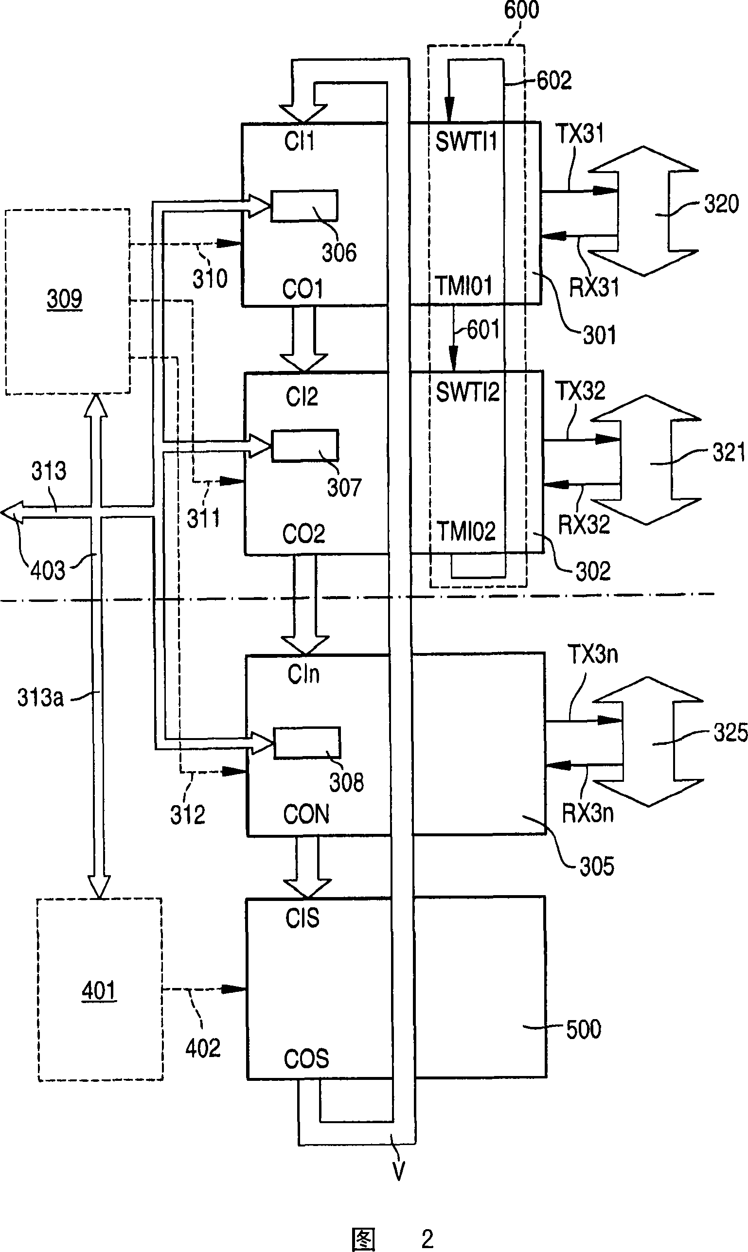
[0030] 100 denotes a gateway subscriber via which bus systems 320 and 321 are connected to one another. This is achieved via bidirectional interface 110 to bus system 320 and via bidirectional interface 111 to bus system 321 . 301 and 302 denote the communication components, wherein the first communication component 301 is coupled to the bus system 320 , ie is used for it, and the second communication component 302 is coupled to the bus system 321 and thus hosts ...


PUM


Abstract

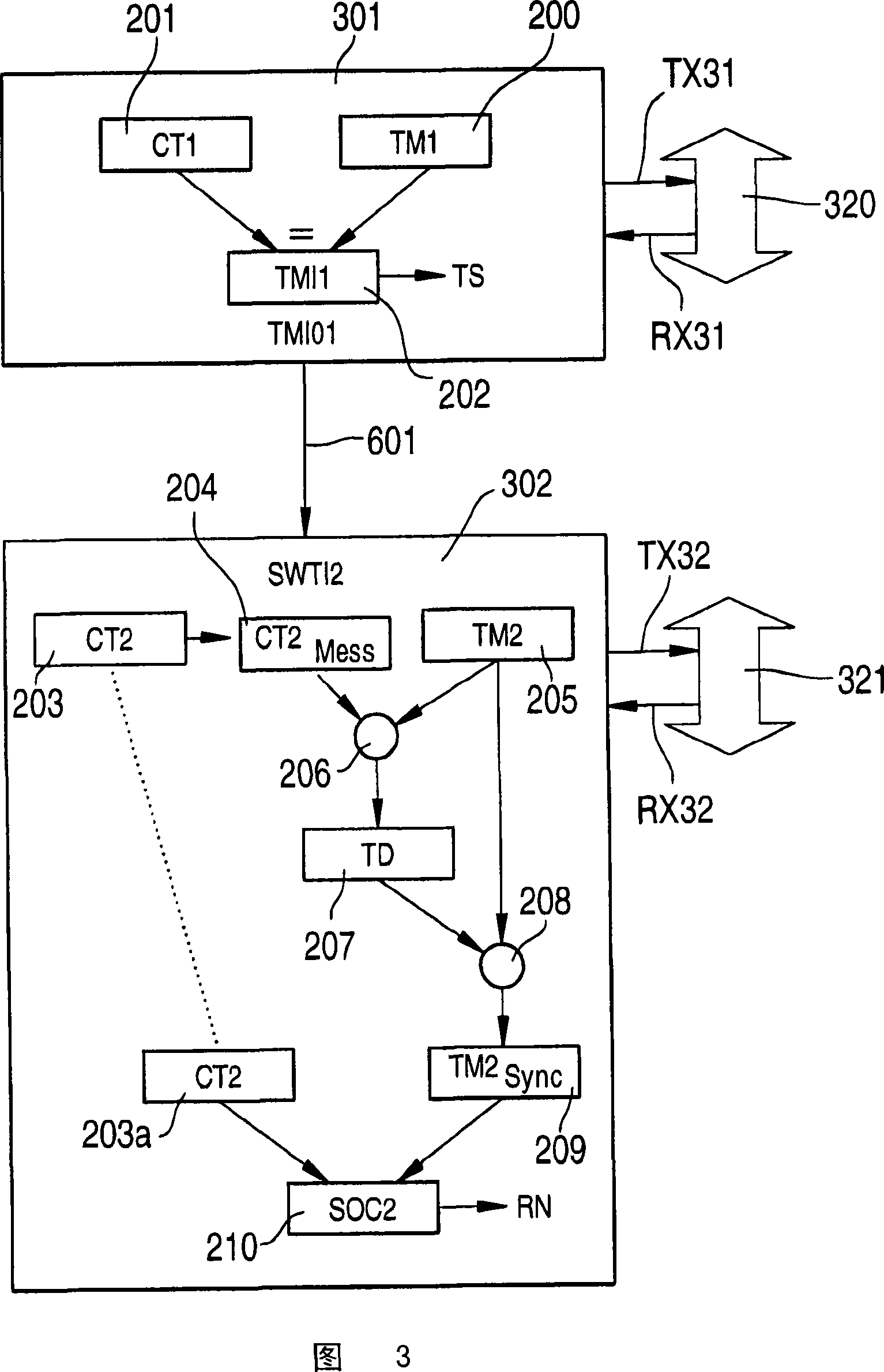
A device for synchronizing at least two bus systems, having a first communications module for a first bus system and a second communications module for a second bus system, wherein in the first communications module first trigger information is present by which a trigger signal is triggered in the first bus system, characterized in that the device is configured in such a manner that the first and second communications modules are connected to each other and the first trigger information is transmitted to the second communications module, and the second communications module is configured in such a manner that a time information value is determined from the first trigger information and that time information value is compared with a second time mark of the second bus system, a time difference being determined and the next reference message being triggered in the second bus system in dependence upon the second time mark and the time difference.

Description

technical field [0001] The invention proceeds from a method and a device for synchronizing two bus systems and a corresponding arrangement comprising two bus systems according to the preambles of the independent claims, wherein the time control takes place via reference messages. Background technique [0002] Such reference messages are used, for example, in FlexRay or in TTCAN for the generation of basic periodic messages on a bus system within the scope of time-controlled communication. Such a bus system is necessary because the networking of control devices, sensors and actuators has increased dramatically in recent years in modern vehicle construction or mechanical engineering, especially in the field of machine tools and in automation. In this case, synergistic effects can be achieved by distributing the functions over several control devices. The communication between the different stations of such a distributed system therefore takes place increasingly via a bus syst...

Claims


Application Information

Patent Timeline
Patent Type & Authority Applications(China)
IPC IPC(8): H04J3/06H04L12/44H04L12/403H04L12/46H04L12/42
CPCH04L7/08H04L12/4625H04J3/0655
Inventor F·哈特维克J·陶布
Owner ROBERT BOSCH GMBH
Learn More