Ejection shaping die

An injection molding and mold technology, applied in the field of injection molding molds, can solve the problems of limited effect, difficulty in production and preparation, and high production cost

Inactive Publication Date: 2008-04-23
HONG FU JIN PRECISION IND (SHENZHEN) CO LTD +1
View PDF1 Cites 3 Cited by
  • Summary
  • Abstract
  • Description
  • Claims
  • Application Information

AI Technical Summary

Problems solved by technology

However, the shape of the nozzle is complicated, making production and preparation difficult, and the production cost is also high; secondly, the heat conduction ring of the nozzle releases the heat from the injection end of the nozzle to the mold, which will increase the temperature of the mold and cause delayed solidification of the molten plastic material
Therefore, the effect of the nozzle on preventing wire drawing is relatively limited, and it is not easy to process and manufacture

Method used


Image

  • Ejection shaping die
  • Ejection shaping die
  • Ejection shaping die

Examples


no. 1 example

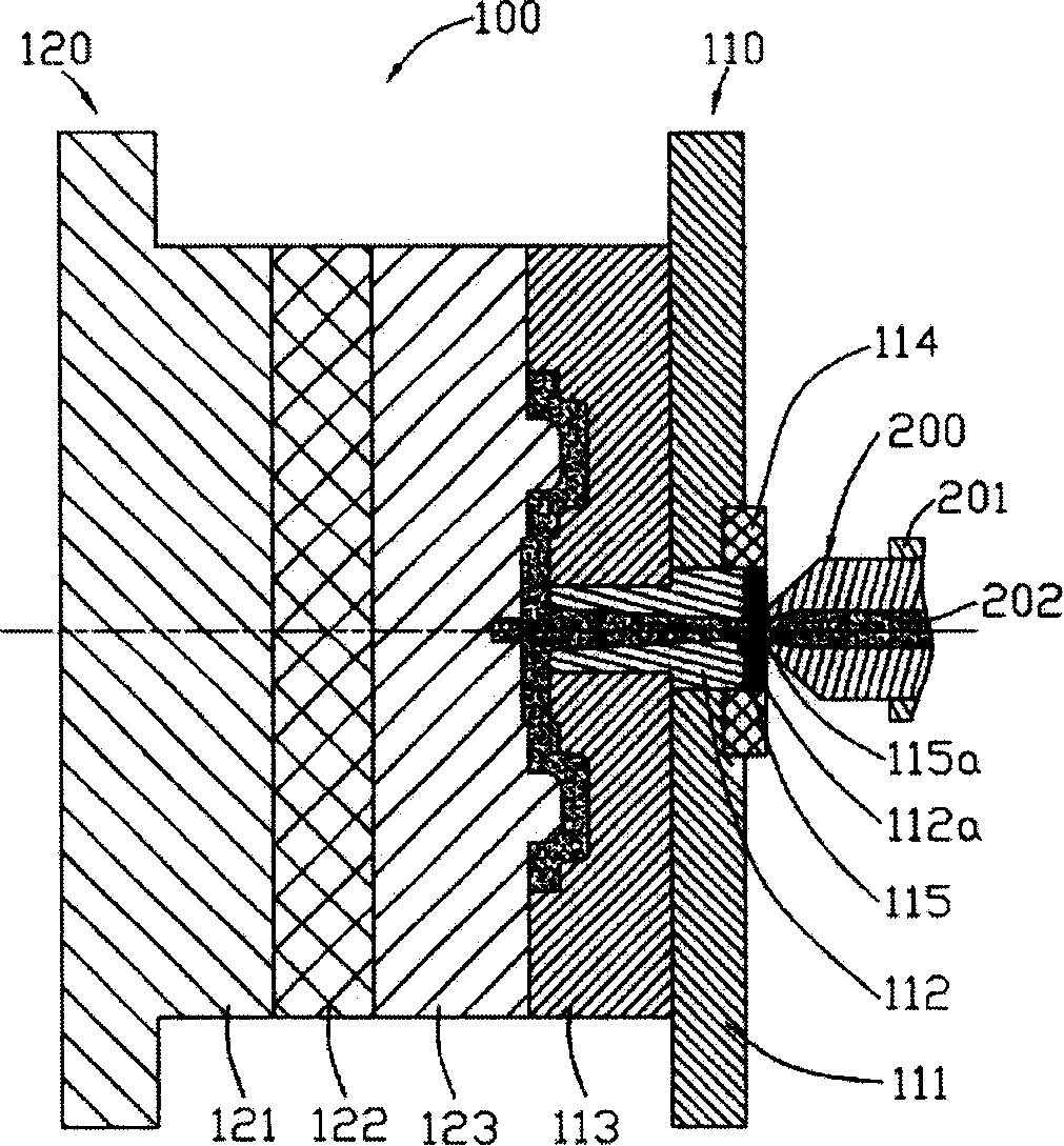
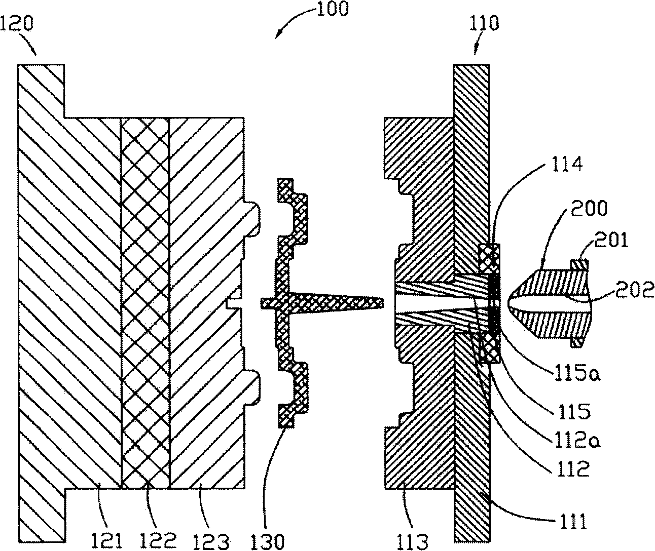
[0015] see figure 1 and figure 2 , the injection molding mold 100 of this embodiment includes a first half-mold 110 and a second half-mold 120. When the first half-mold 110 and the second half-mold 120 cooperate, an injection cavity can be formed for molding the corresponding structure. product. The first half-mold 110 and the second half-mold 120 can move relatively, that is, when the first half-mold 110 is fixed, the second half-mold 120 can be controlled to move toward the first half-mold 110 to cooperate to form a mold cavity. Of course, when the second half-mold 120 is fixed, the first half-mold 110 can be controlled to move toward the second half-mold 120 to cooperate to form the mold cavity. When manufacturing a molded product, after the first half-mold 110 and the second half-mold 120 are closed to form a mold cavity, the nozzle 200 fixed on the spray gun is injected into the mold cavity through the sprue 112a in the sprue bushing (Sprue Bush) 112 The molten plast...

no. 2 example

[0023] See image 3 , The mold structure of the second embodiment of the technical solution is basically the same as that of the first embodiment, except for the sprue bushing. In order to match the shape of the nozzle 300, the end of the sprue bushing 212 of the second embodiment that matches the nozzle 300 is a bowl-shaped structure, and the surface that matches the nozzle 300 is a bowl-shaped concave surface. The thermal insulation layer 215 is adapted to the structure of the sprue bushing 212, that is, the thermal insulation layer 215 also has a bowl-shaped structure, and the surface in contact with the sprue bushing 212 is the same bowl-shaped concave surface as the surface of the sprue bushing 212 . The heat insulating layer 215 has a hole 215a, and the diameter of the hole 215a is similar to the diameter of the sprue 212a. Preferably, the diameter of the hole 215a ranges from 95% to 105% of the diameter of the sprue 212a.

no. 3 example

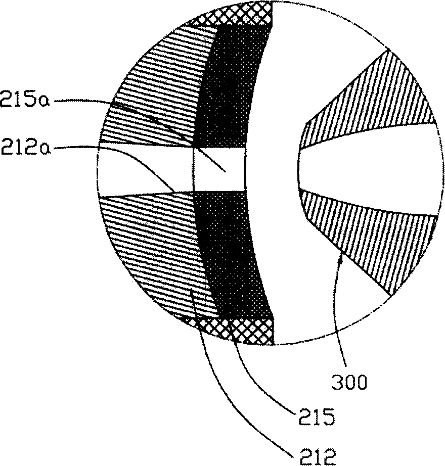
[0025] Of course, the structure of the heat insulating layer does not necessarily need to be exactly the same as that of the nozzle, as long as the shape and structure of the heat insulating layer and the sprue bushing corresponding to the outer surface of the nozzle are consistent and fully in contact. For example, see Figure 4 The heat insulation layer 315 of the third embodiment of the technical solution includes a first heat insulation part 315a and a second heat insulation part 315b, the first heat insulation part 315a is a bowl-shaped structure corresponding to the nozzle 400, and the structural shape of the second heat insulation part 315b Not limited thereto, for example, it may be a ring structure surrounding the first heat insulating portion 315a. The first heat insulating portion 315a has a hole 315c whose diameter is similar to that of the sprue 312a. Preferably, the diameter of the hole 315a ranges from 95% to 105% of the diameter of the sprue 312a.

[0026] In...


PUM

PropertyMeasurementUnit
thicknessaaaaaaaaaa

Abstract

The present invention provides an ejection forming mould. Said mould includes a mould base body, said mould base body possesses an injection channel liner, on the external surface of said injection channel liner which is used for matching with ejection machine nozzle a heat-insulating layer is set. In the invented technical scheme said heat-insulating layer can isolate most of heat quantity released from nozzle and transferred to the mould and can ensure cooling effect of mould cooling system, therefore it can avoid the production of superhigh temperature in mould injection channel and can prevent the moulded product from producing wire-drawing phenomenon.

Description

technical field [0001] The invention relates to a mold, in particular to an injection molding mold. Background technique [0002] Injection molding mold refers to the mold used for high-pressure injection molding due to the high viscosity of molten plastic. Injection molding molds are usually divided into two parts: the die and the punch. When molding, the die and punch are closed to form a cavity, and the nozzle body injects molten plastic into the cavity through the gating system; then, the sprue is closed and enters the pressure holding stage to maintain the pressure to compensate for the cooling and solidification of the material in the mold. The resulting volume shrinkage; then enter the cooling stage, the product in the mold is further cooled, and when it is solidified to be able to be demolded smoothly, the concave mold and the convex mold are separated to take out the product. In actual production, the temperature of the injection channel of the mold is often too h...

Claims


Application Information

Patent Timeline
Patent Type & Authority Applications(China)
IPC IPC(8): B29C45/27B29C45/17
Inventor 杜健生
Owner HONG FU JIN PRECISION IND (SHENZHEN) CO LTD
Why Eureka
Try Eureka