Automatic focusing optical lens module

An optical lens and auto-focus technology, applied in optics, optical components, installation, etc., can solve the problems of non-commercial value utilization, increase manufacturing processing, and precision processing of related components, achieve high industrial utilization value, and improve driving torque , the effect of reducing the volume

Inactive Publication Date: 2008-04-23
IND TECH RES INST
View PDF9 Cites 10 Cited by
  • Summary
  • Abstract
  • Description
  • Claims
  • Application Information

AI Technical Summary

Problems solved by technology

However, as digital cameras gradually replace traditional cameras, and mobile phone lenses with telescopic and zoom functions have gradually become fashionable commodities and the trend of standard equipment for mobile phones, the above-mentioned large conventional ultrasonic motors (or piezoelectric motors) or piezoelectric It is difficult to accommodate the actuator, which is the main reason why the size of the optical lens body is still very large in digital cameras or camera phones.
[0010] In addition, in addition to the above-mentioned prior patents, although some papers or seminars have seen digital cameras or camera phones with small piezoelectric optical lenses, the components of the existing piezoelectric optical lenses are quite complicated, and related components cannot be used. Batches of precision processing to complete, must be processed separately
Moreover, because the components of the existing piezoelectric optical lens are quite complicated, in addition to increasing the difficulty of manufacturing and processing, its assembly method is also quite complicated, especially the assembly method of the piezoelectric stator is quite difficult, thus detracting from the simple piezoelectricity. The driving force of the optical lens, especially the small components cannot be completed by automatic machines, which also increases manpower consumption and manufacturing costs
Therefore, although the existing piezoelectric optical lens has the advantage of small size, it does not have any competitive advantage in cost, so it does not have commercial value or industrial utilization
[0011] In view of the above-mentioned shortcomings of the prior art, how to provide a piezoelectric optical lens to achieve the functions of simple components, large driving torque, small size, firm structure, easy manufacture and convenient assembly, and then overcome the problems existing in the background technology, is It has become a problem that the industry needs to overcome urgently

Method used


Image

  • Automatic focusing optical lens module
  • Automatic focusing optical lens module
  • Automatic focusing optical lens module

Examples


Embodiment Construction

[0027] The specific embodiments of the present invention are described below with reference to the accompanying drawings, so that those skilled in the art can easily understand the technical features and effects of the present invention.

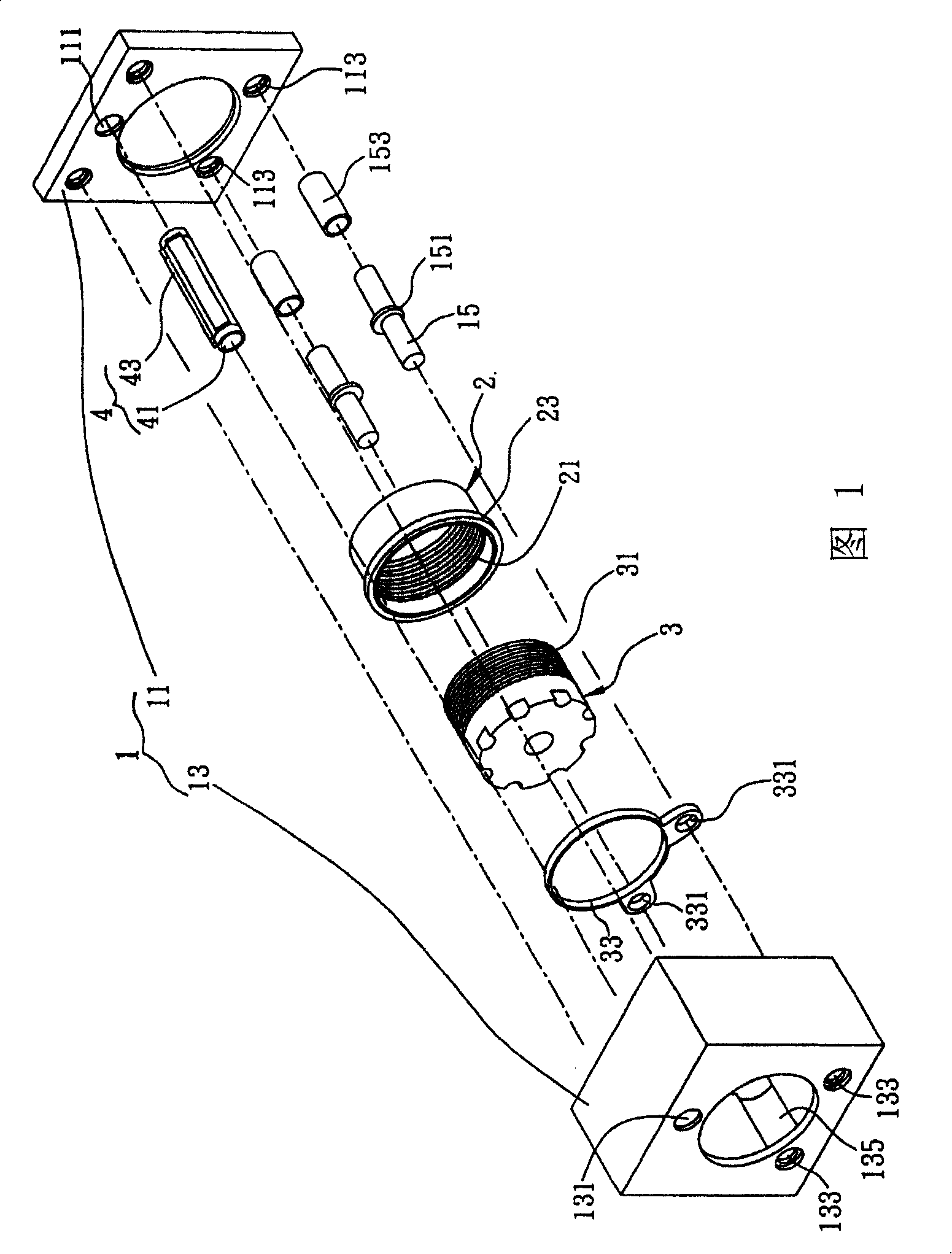
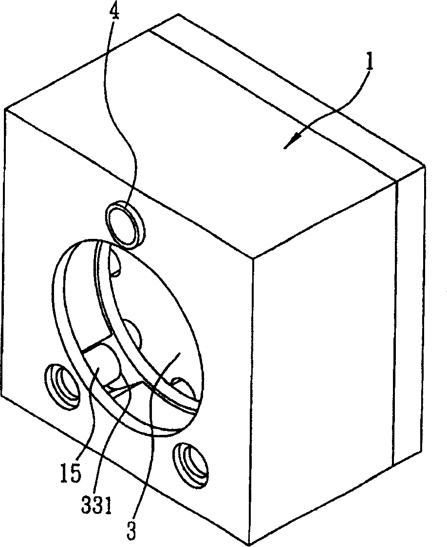
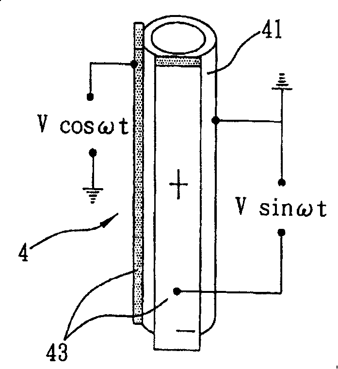
[0028] Figure 1 and figure 2 As shown, the present invention provides an auto-focus optical lens module, which includes a seat body 1 with an accommodation space, a sleeve 2 rotatably positioned in the accommodation space 1, a lens 3 screwed to the sleeve 2, and a piezoelectric component 4 fixed in the base body 1 for contacting and driving the rotation of the sleeve 2, the base body 1 and the lens 3 are respectively provided with a first guide part 15 and a second guide part for corresponding sliding positioning 331, so that the lens 3 can be converted and driven to focus by driving the sleeve 2 to rotate, so that the autofocus optical lens module with simple components improves the driving force and overcomes the shortcomings of complex co...


PUM


Abstract

The invention comprises a base with a holding space, a sleeve barrel located in the holding space, a lens connected to the sleeve barrel, and a piezoelectric assembly secured in the holding space and used for driving the sleeve barrel to rotate. Between the base and the lens there are a first and second guiding units used for driving the lens to focus after rotating the sleeve barrel.

Description

technical field [0001] The invention relates to a driving technology of an optical lens, in particular to an automatic focusing optical lens module. Background technique [0002] My Taiwan Certificate No. M294046 New Patent discloses an autofocus lens module, which consists of a bottom cover, two guide pins, two conductive sheets, a lower frame, a lens sleeve, two springs, a lens, a coil, an upper frame, It consists of two magnets and an upper cover. The bottom cover is a rectangular frame body, four corners of which are provided with four fastening brackets for fastening and integration with the upper cover, a perforation is provided at the center for forming the optical path of the lens, and two fixing brackets are provided at the opposite corners of the inner surface. The holes are used to insert a guide pin respectively; the two conductive sheets are respectively pasted on the bottom cover to connect different electrodes, and a central hole is set between the two conduc...

Claims


Application Information

Patent Timeline
Patent Type & Authority Applications(China)
IPC IPC(8): G02B7/09
Inventor 苏汉威胡朝彰沈圣智
Owner IND TECH RES INST
Why Eureka
Try Eureka