Joint tool and method for flexible printed circuit board

A technology for flexible printing and laminating fixtures, applied in printed circuits, printed circuit manufacturing, electrical components, etc., can solve problems such as reducing the efficiency of hot presses, difficult to control the amount of glue overflowing, and prolonging the time of the pressing process. , to improve the efficiency, reduce the false lamination process, not easy to stick and deform

Inactive Publication Date: 2008-04-23
BYD CO LTD
View PDF0 Cites 24 Cited by
  • Summary
  • Abstract
  • Description
  • Claims
  • Application Information

AI Technical Summary

Problems solved by technology

[0017] In order to control the amount of glue overflow, the whole roll of cover film is pre-baked. The effect of temperature difference between the inside and outside of the whole roll of cover film is large, and uneven baking is prone to occur. It is difficult to control the amount of glue overflow evenly.
Set

Method used


Image

  • Joint tool and method for flexible printed circuit board
  • Joint tool and method for flexible printed circuit board
  • Joint tool and method for flexible printed circuit board

Examples


Embodiment 1

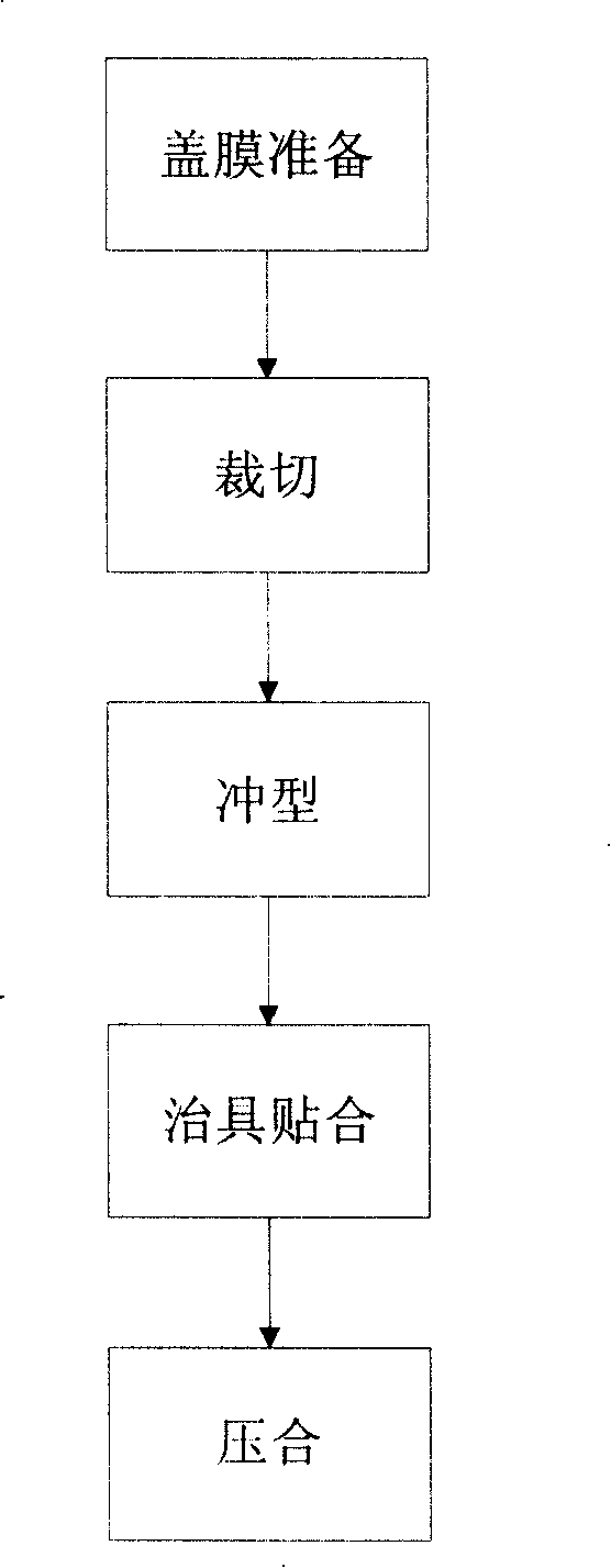
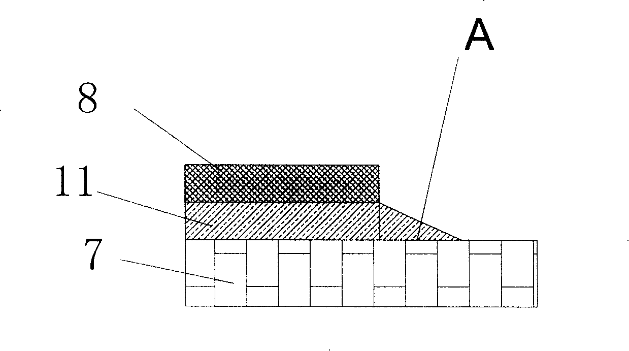
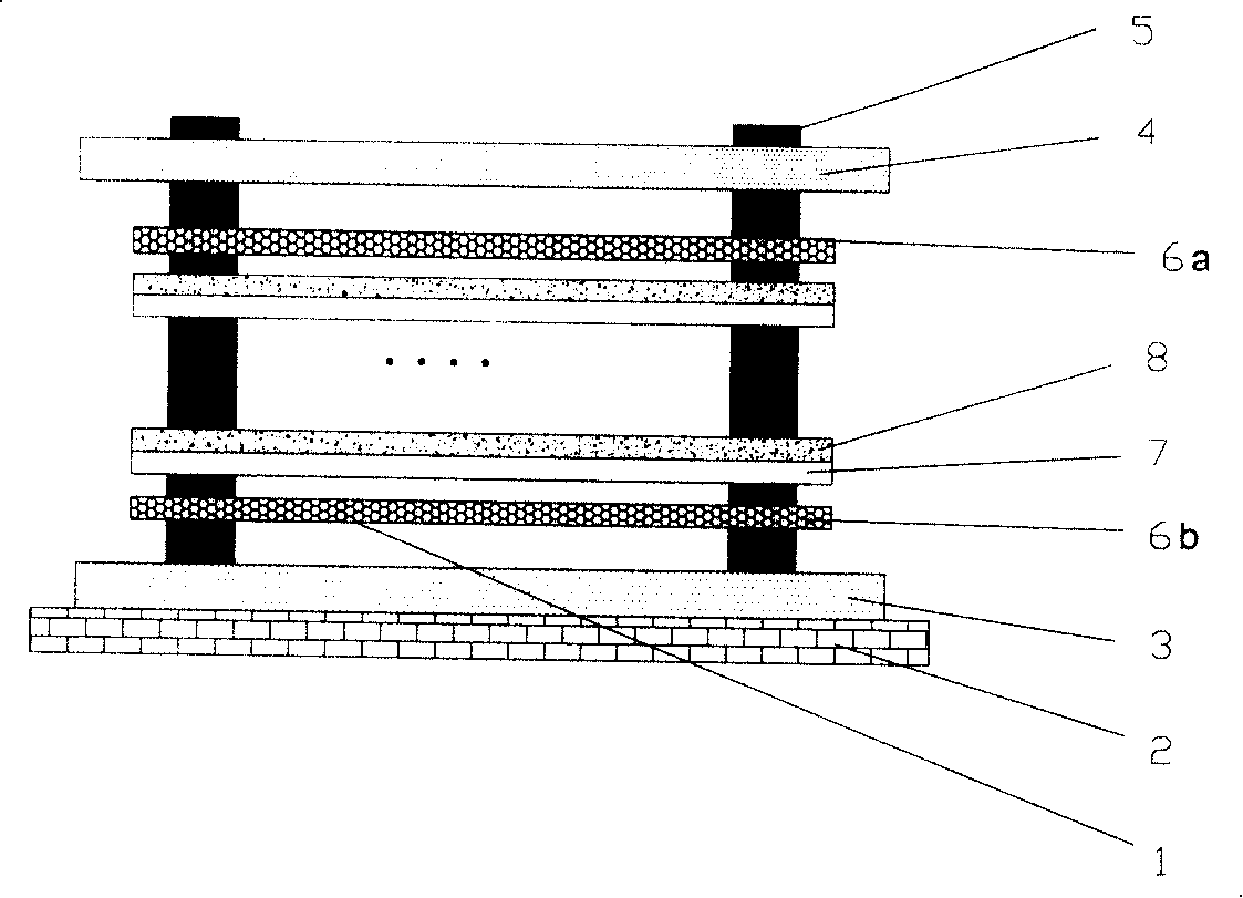
[0077] Embodiment 1, the jig bottom plate 2 , the jig support plate 3 and the jig top cover plate 4 in the single-sided flexible printed circuit board bonding jig 1 are all made of FR4 material. The upper and lower separation membranes (6a, 6b) use polypropylene membrane material with a thickness of 50um. After the circuit is formed, the diameters of the bonding positioning holes on the copper foil 7 and the covering film 8 are both 2.0mm. The jig pin 5 is made of steel with a diameter of 1.97 mm. The bonding level of the product is 15 layers, and the base film of the cover film material is polyimide, with a thickness of 25um; the adhesive 11 of the cover film is epoxy resin, with a thickness of 25um. After bonding, the temperature of the baking process in step 5 is 100° C., and the baking time is 20 minutes, and then the bonding is performed in step 6 of the hot pressing process.

Embodiment 2

[0078] Embodiment 2, the jig bottom plate 2 , the jig supporting plate 3 and the jig top cover plate 4 in the single-sided flexible printed circuit board bonding jig 1 are all made of steel. The upper and lower separation membranes (6a, 6b) use TPX material with a thickness of 50um. After the circuit is formed, the diameters of the bonding positioning holes on the copper foil 7 and the covering film 8 are both 2.0mm. The jig pin 5 is made of steel with a diameter of 1.97mm. The bonding level of the product is 15 layers, and the base film of the cover film material is polyimide, with a thickness of 25um; the adhesive 11 of the cover film is epoxy resin, with a thickness of 25um. After bonding, the baking temperature in step 5 is 100° C. and the baking time is 20 minutes, and then the bonding is performed in step 6 in the hot pressing process.


PUM

PropertyMeasurementUnit
Thicknessaaaaaaaaaa

Abstract

The method includes steps in sequence: in fixture jointing step, multilaminar copper foils with cover layers to be integrated closely and corresponding cover layers are lined up and piled together through pins of the fixture, and pins are pulled out after well piled; in baking step, putting the fixture, multilaminar copper foils and cover layers in the fixture into heater unit to be baked; in pressfitting step, placing baked copper foils and cover layers into hot-press to be pressed. The fixture includes pins, supporting board in use for supporting product, and top cover plate in use for cooperating with supporting board to clamp product. There are location holes, which are corresponding to the mating holes on product, on the supporting board and on the top cover plate. The pins can be inserted into the location holes, and pulled out from the location holes. Advantages are: raised jointing precision and efficiency, and controlling quantity of overflowed glue effectively.

Description

【Technical field】 [0001] The invention relates to a bonding fixture and a bonding method for a flexible printed circuit board, in particular to a bonding fixture and a method for bonding a cover film to a copper foil during the production process of a flexible printed circuit board. 【Background technique】 [0002] Electronic products are developing towards the trend of light, thin, short and small, which makes FPC (flexible printed circuit board) quickly shift from military use to civilian use, and to consumer electronics products. In recent years, almost all high-tech electronic products have used flexible printed circuit boards in large quantities. A Japanese scholar once said that almost all electrical products use flexible printed circuit boards inside. With the miniaturization of electronic products, various electronic components are also developing in the direction of miniaturization and miniaturization. Flexible printed circuit boards carrying various electronic comp...

Claims


Application Information

Patent Timeline
IPC IPC(8): H05K3/00
Inventor 尤健
Owner BYD CO LTD
Why Eureka
Try Eureka