Straight line shock device

An impact device and straight line technology, applied in the field of impact devices, can solve problems such as increasing instantaneous speed, consumption, and increasing the power of impact tools

Inactive Publication Date: 2008-04-30
吴纯培
View PDF0 Cites 11 Cited by
  • Summary
  • Abstract
  • Description
  • Claims
  • Application Information

AI Technical Summary

Problems solved by technology

For an impact piston with a determined size and stroke, to make it obtain as large an impact force as possible, the method used in the prior art is to make the impact piston obtain as large an acceleration as possible and move forward; for this purpose, currently No matter whether its power system is powered by electricity or compressed air, it works on the impact piston during the impact stroke to make it accelerate to increase the instantaneous speed before impact; at the same time, in order to impact the impact piston Backward reverse, or in order not to damage the power part of the impactor, it is necessary to give a reverse force (or air cushion) before the impact piston impacts. In addition, the impact return also consumes some work.
Existing various impact tools like this have to increase the power to the impact tool through the power system in order to obtain a larger impact force.

Method used


Image

  • Straight line shock device
  • Straight line shock device
  • Straight line shock device

Examples


Embodiment Construction

[0028] The present invention will be described in further detail below in conjunction with the accompanying drawings.

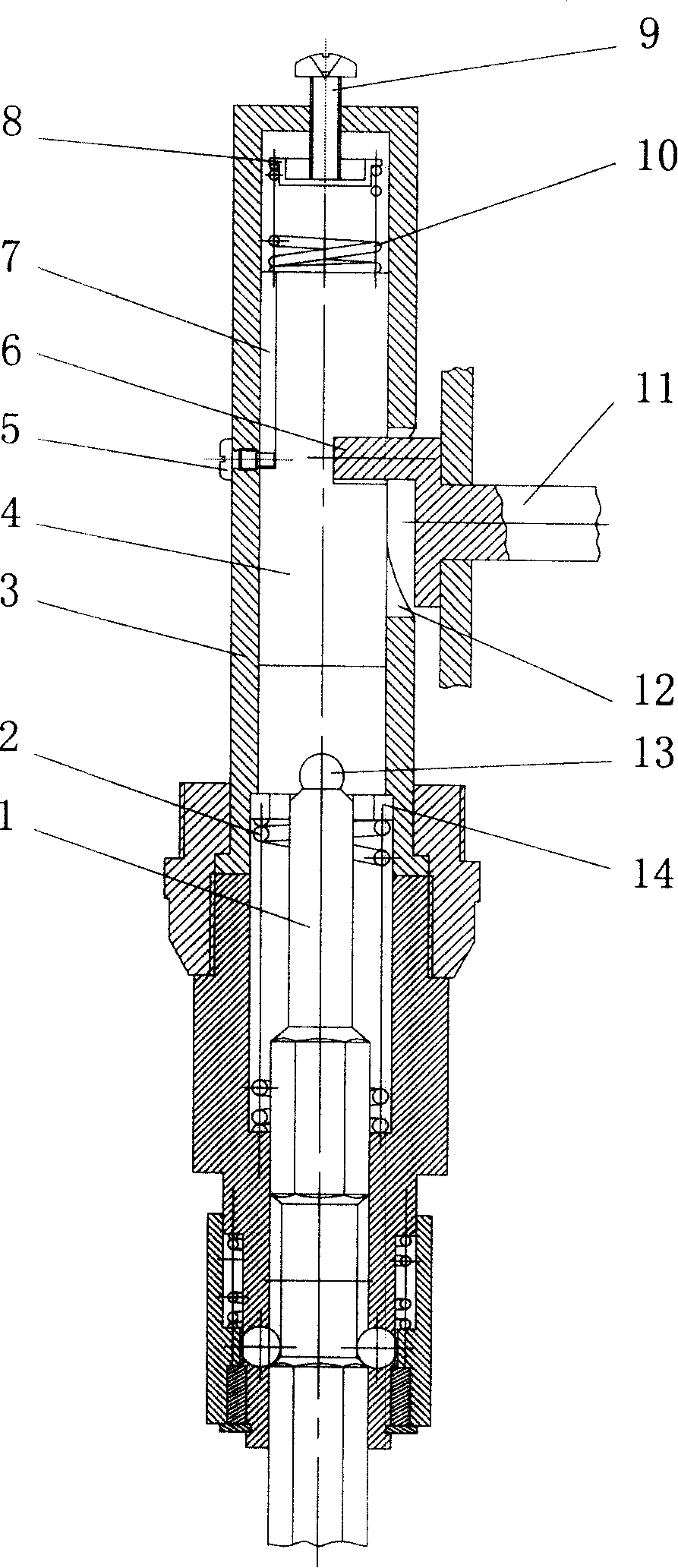
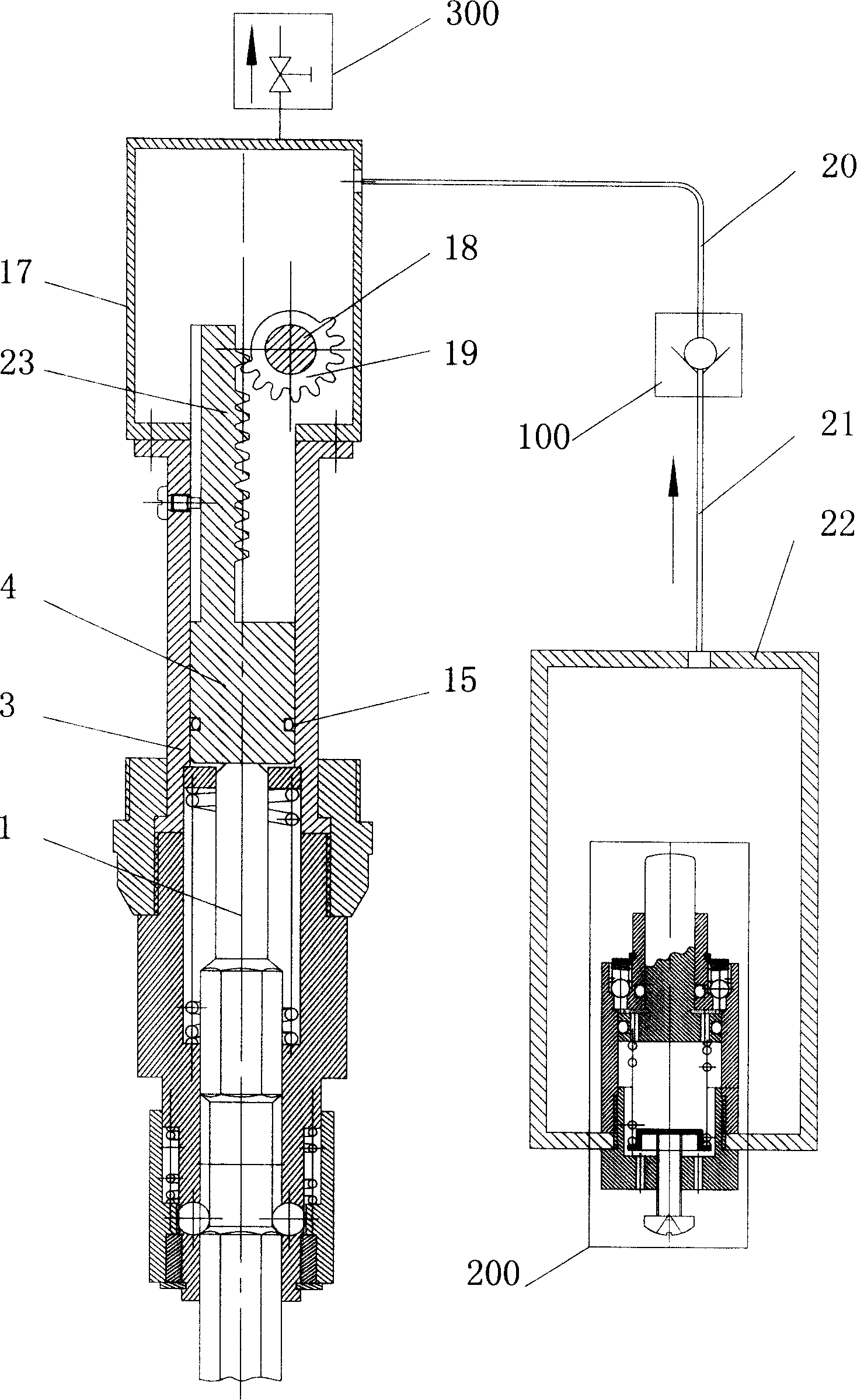
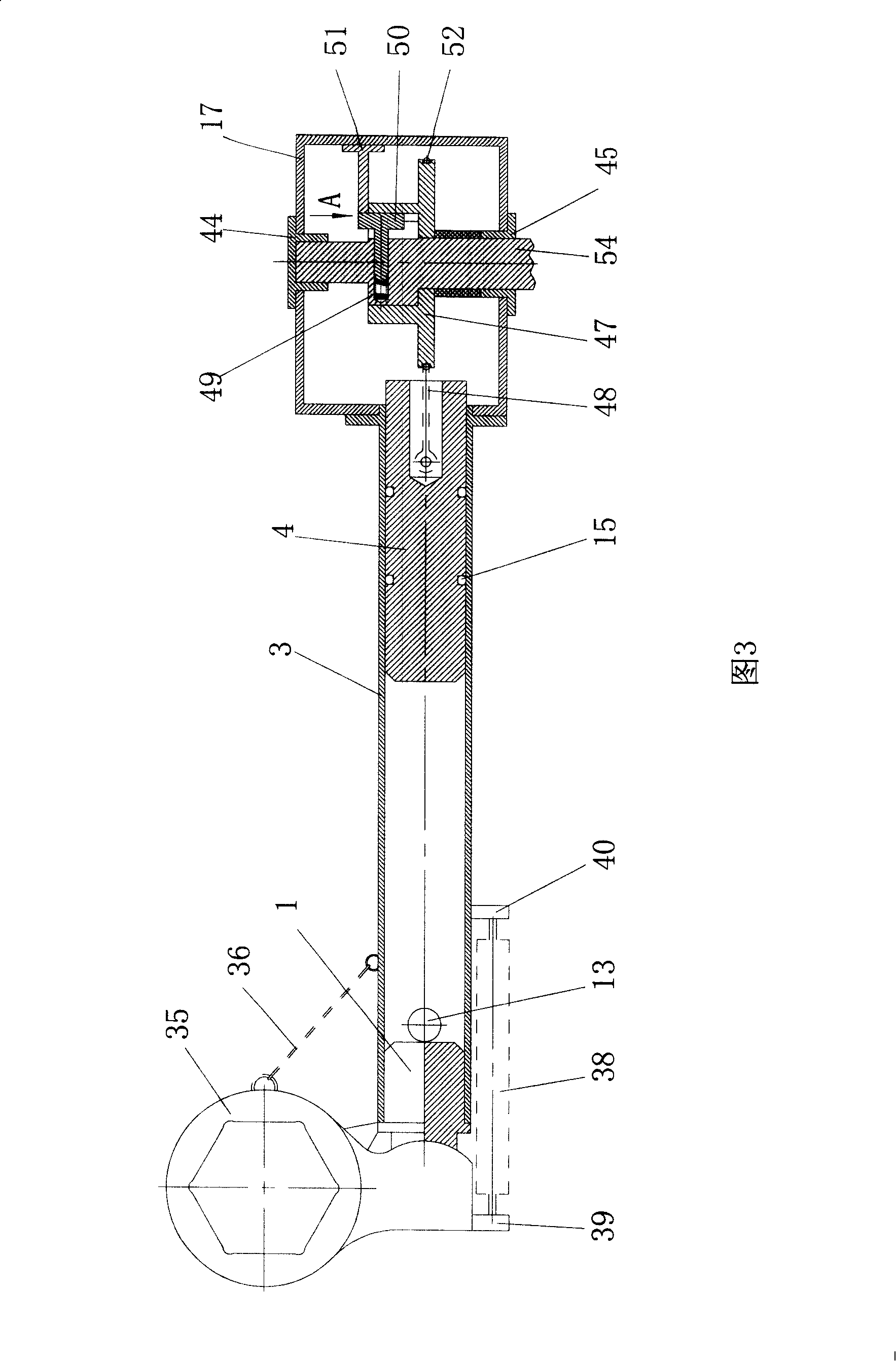
[0029] figure 1 Shown is a schematic structural view of applying an embodiment of the present invention to an electric (pneumatic) pick. Wherein, the lifting and disengaging mechanism is composed of a crankshaft 11 connected to the power system and capable of rotating under the action of the power system, and a bellcrank pin 6 fixed to the crankshaft 11. The impact piston 4 is provided with grooves 406 in the axial and circumferential directions. The groove 406 is L-shaped; the bellcrank pin 6 is embedded in the groove 406, and the part embedded in the groove 406 is made into a rod shape, and its cross-section is arcuate or the shape of the remaining part after the circle is excised by an arcuate portion, as shown in the figure 4. The accumulator includes an elastic element 10 and a gland 8. The gland 8 and the impact piston 4 are located at both ends of th...


PUM


Abstract

The invention discloses a linear impact device, including a power system, an impact anvil, an impart plunger, a cylinder of straight tube shape for holding the impact plunger, a promotion and detachment mechanism connected with the power system and the impact plunger and a power accumulator for accumulating power by compressing air or by compressing elastic elements. The power accumulator and the impact anvil are respectively arranged at the two ends of the cylinder. In the time of impact return, the power system provides power for the promotion and detachment mechanism to drive the impact plunger to move towards the direction of the power accumulator, the impact plunger then compresses the air the elastic elements of the power accumulator to accumulate power, and in the time of impact stroke, the promotion and detachment mechanism disengages from the impact plunger. The invention applies work to the impact plunger when the impact plunger is in the time of impact return, power is accumulated, the accumulated power is transmitted to the impact plunge when the impact plunge is in the time of impact stroke facilitating the impact plunger to impact the impact anvil, thereby the process of doing work is stable and safe, the impact power is large, and the damage on the power system and various driving parts is small.

Description

technical field [0001] The invention relates to an impact device, which can be applied to impact tools such as pneumatic picks, electric picks, pneumatic hammers, electric hammers, wind rock drills, electric rock drills, wind wrenches, electric wrenches and manual impact booster wrenches. Background technique [0002] Impact occurs when two objects collide. In the impact tool, the active part used for impact is generally called the impact piston; while the impacted part has various names in various impact tools, such as impact lining head, drill bit, chisel, etc., the impacted part It can be called impact anvil. The movement of the impact piston before the impact is called the impact stroke, and the movement of the impact piston after the impact is called the impact return stroke. [0003] The active part of the impact must obtain energy to impact the piston, and the impact can only be achieved by generating speed. The more energy it obtains, the greater the instantaneous ...

Claims


Application Information

Patent Timeline
Patent Type & Authority Applications(China)
IPC IPC(8): B25D17/00B25D17/06F15B1/02F16F1/00
Inventor 吴纯培
Owner 吴纯培
Why Eureka
Try Eureka