
Voltage stabilizer comprising accelerated return for output

A voltage regulator and voltage technology, applied in instruments, regulating electrical variables, control/regulating systems, etc., can solve problems such as slow discharge speed, small driving current, and inability to respond quickly.

Inactive Publication Date: 2008-04-30
HOLTEK SEMICON
View PDF1 Cites 12 Cited by
  • Summary
  • Abstract
  • Description
  • Claims
  • Application Information

AI Technical Summary

Problems solved by technology

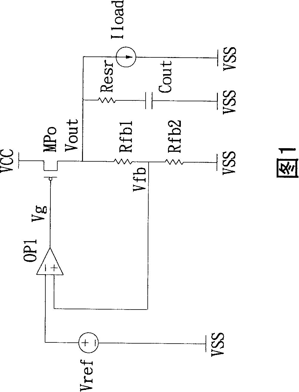
[0002] Please refer to FIG. 1 , which is the circuit structure of the prior art low dropout voltage regulator. When the output current of the low dropout voltage regulator (Low Dropout Voltage Regulator, LDO) circuit changes, the OP operational amplifier can respond in time to make the output The voltage is maintained at a certain value, so the stability of the circuit is maintained, but if the output current drops from a high current value to an extremely low current value (for example: 500mA to 0A), the output voltage will be pulled up instantaneously and cannot be recovered in a short time. The reason is that the OP operational amplifier needs a period of time to adjust its response, and its original output to the P-channel Metal Oxide Semiconductor Field Effect Transistor (P-Channel Metal Oxide Semiconductor Field Effect Transistor, P-MOSFET) begins to charge the output capacitor , so the output voltage is also pulled up accordingly. After the OP operational amplifier responds and adjusts and the output capacitor is charged, the current output to the P-MOSFET is cut off, and the output voltage needs to be discharged simultaneously by the feedback resistors Rfb1 and Rfb2, but generally In order to achieve the purpose of power saving, the prior art low-dropout voltage regulator will select larger resistance values ​​Rfb1 and Rfb2 for circuit matching. Relatively speaking, the discharge speed of these two feedback resistors for the output voltage becomes extremely slow, requiring It takes hundreds of milliseconds to discharge to stabilize the output voltage again
[0003] In addition, please refer to U.S. Patent U.S5864227 for the circuit architecture of another prior art low-dropout voltage regulator. Its FIG. Set the voltage for comparison. If Vg is greater than the preset voltage, the P-MOSFET will be turned on to quickly reduce the output voltage Vout and produce a voltage stabilization effect. However, this architecture has disadvantages, and its reference voltage Vg cannot quickly respond to Vout Voltage, when Vout rises, it must be reacted by its OP operational amplifier (OP1) before Vg changes, so the effect of this voltage regulator is still not good
In addition, the step-down transistor used in this circuit is composed of P-MOSFET components, and the discharge performance of this component is not good, because it requires a small driving current and cannot achieve the purpose of quickly discharging current, so there is still an improvement Space

Method used


Image

  • Voltage stabilizer comprising accelerated return for output
  • Voltage stabilizer comprising accelerated return for output
  • Voltage stabilizer comprising accelerated return for output

Examples


Embodiment Construction

[0033] Now coordinate the following drawings to illustrate the detailed structure of the present invention and its connection relationship.

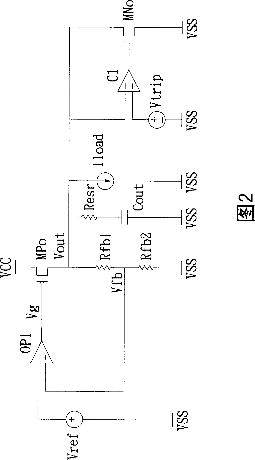
[0034] Please refer to FIG. 2, which is the first implementation structure of the circuit of the low-dropout voltage regulator of the present invention, wherein the negative feedback terminal of the operational amplifier OP1 is grounded, so that the voltage of the feedback voltage reference point Vfb is close to the reference voltage Vref. This structure can adapt to different The change of the output voltage Vout, its Vref voltage is easy to compare with the Vfb voltage to detect the change of Vout, so the purpose of quickly discharging Vout can be realized.

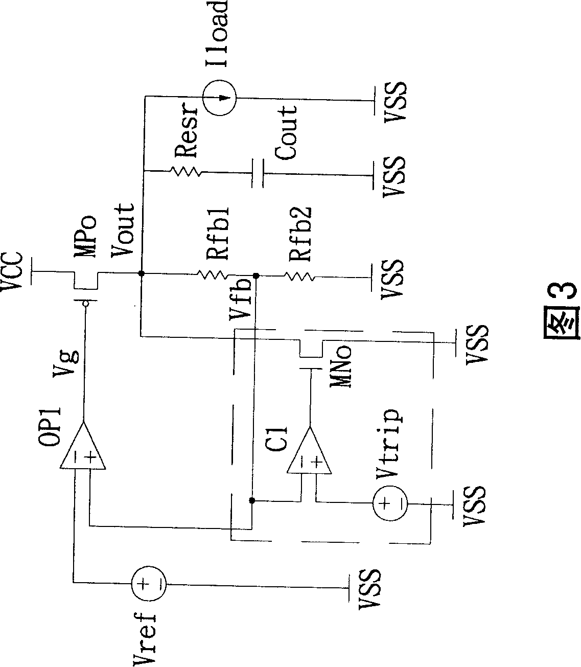
[0035] Please refer to FIG. 3, which is the second implementation structure of the circuit of the low-dropout voltage regulator of the present invention, and its overall structure includes: operational amplifier OP1, comparator C1, voltage output transistor MPo, step-down transisto...


PUM


Abstract

The invention provides a voltage stabilizer comprising output accelerated replies. A comparer and a voltage-dropping transistor are added between the negative and the positive voltage feedback input ends of an operational amplifier of a low-voltage stabilizer. The comparer is used for detecting voltage the changes of a reference potential point positioned between a first feedback resistor and a second feedback resistor. If the voltage of the reference potential point is higher than a preset voltage, the voltage-dropping transistor can be immediately turned on so that the output voltage can be swiftly decreased to produce excellent voltage stabilization effect.

Description

technical field [0001] The present invention relates to a voltage stabilizer including output acceleration recovery, in particular to a comparator and a step-down transistor added between the voltage positive feedback input terminals of the operational amplifier of a traditional low voltage stabilizer, the comparator is used to detect the reference The voltage change of the potential point (that is, the voltage positive feedback input terminal of the operational amplifier), the more precise position of the reference potential point is between the first feedback resistor and the second feedback resistor, if the voltage of the reference potential point is greater than the preset voltage , that is, the step-down transistor (which is an N-MOSFET) is turned on, so as to reduce the output voltage Vout rapidly, so as to produce an excellent voltage stabilizing effect. Background technique [0002] Please refer to FIG. 1 , which is the circuit structure of the prior art low dropout ...

Claims


Application Information

Patent Timeline
Patent Type & Authority Applications(China)
IPC IPC(8): G05F1/56
Inventor 林仲威
Owner HOLTEK SEMICON
Learn More