
Electric spring operation machine for switch device

A technology of electric springs and switchgear, which is applied to the power device inside the switch, electric switch, high-voltage/high-current switch, etc. It can solve the problems of non-parallel between plates, troublesome adjustment, improper adjustment, etc., and achieve high corner accuracy and transmission The effect of less loss and fewer parts

Active Publication Date: 2008-04-30
西安西电高压开关操动机构有限责任公司 +1
View PDF0 Cites 16 Cited by
  • Summary
  • Abstract
  • Description
  • Claims
  • Application Information

AI Technical Summary

Problems solved by technology

However, the single-layer area with only two side plates still requires a more accurate distance between the plates. The distance is adjusted by the nut on the connecting screw between the two side plates. The adjustment is troublesome, and the accuracy of the distance is greatly affected by the human factors of assembly adjustment. , Improper adjustment may cause non-parallel between plates

Method used

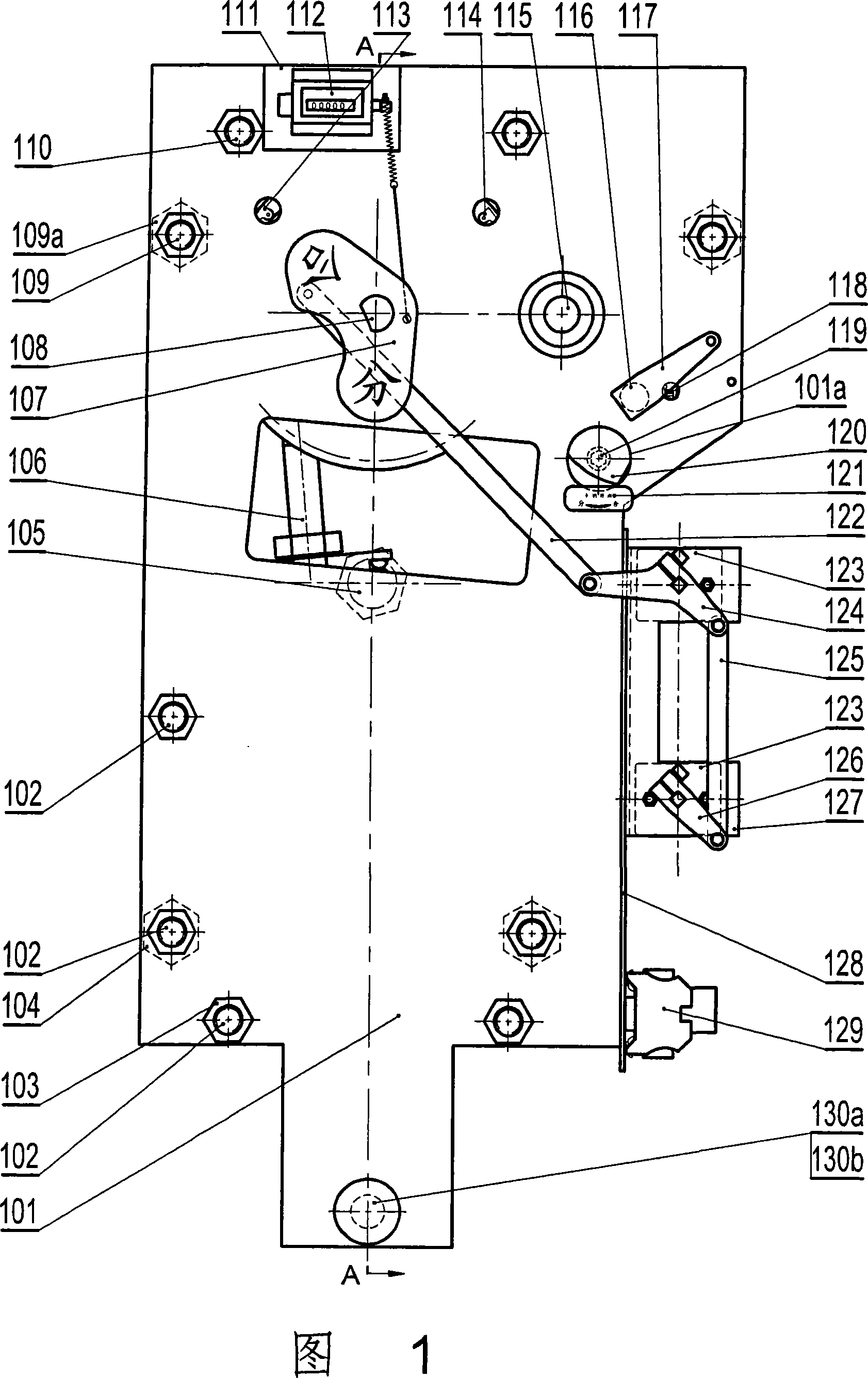
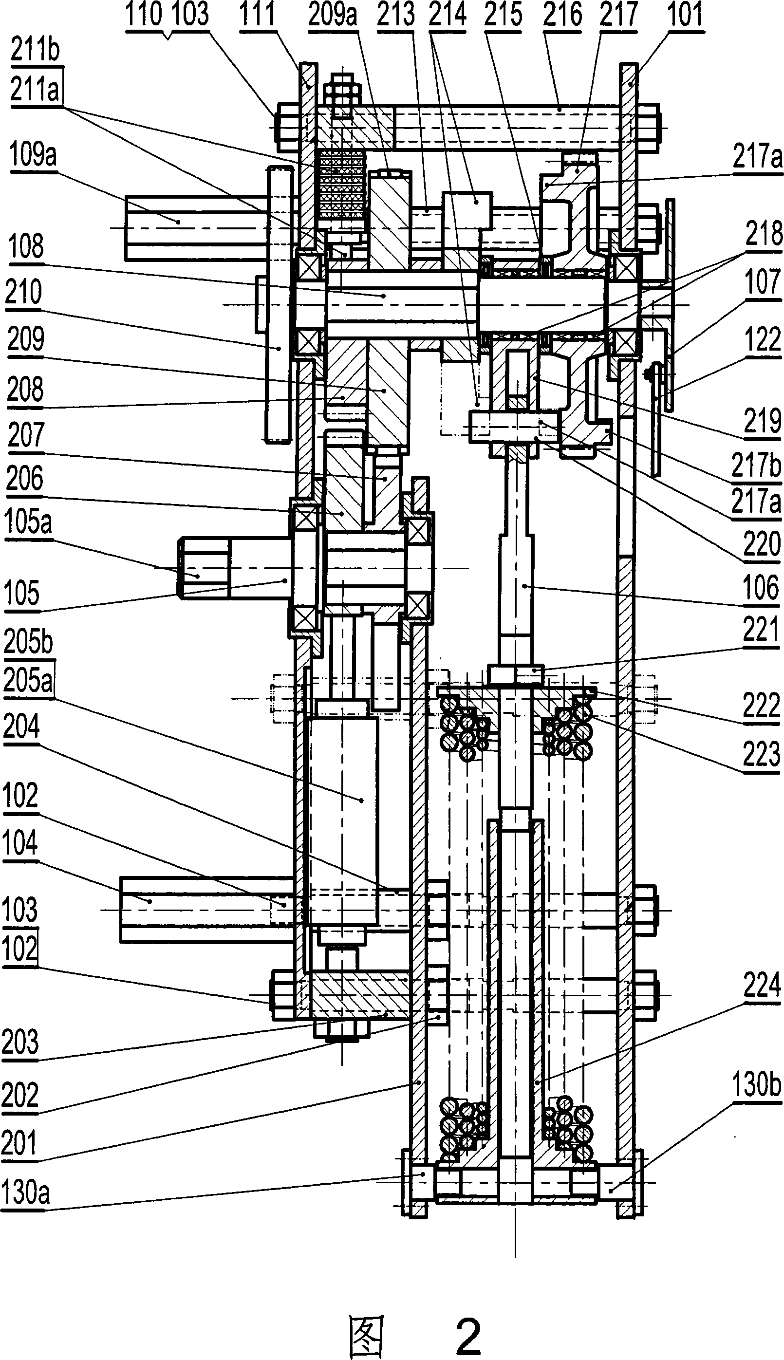
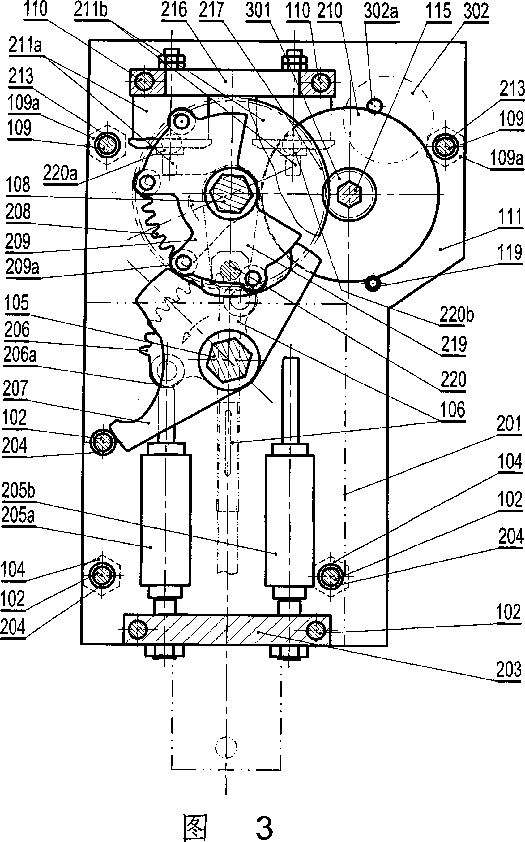

Image

  • Electric spring operation machine for switch device
  • Electric spring operation machine for switch device
  • Electric spring operation machine for switch device

Examples


Embodiment 1

[0027] Embodiment 1 The steering direction of the output shaft of the mechanism is: clockwise when the brake is closed, and counterclockwise when the brake is opened.

[0028]As shown in Figure 1, the mechanism main shaft 108 protrudes from the flat shaft end of the panel, and an indicator plate 107 is fixed on which the dividing and closing signs are housed. When the opening (or closing) gate is in place, the opening (or closing) sign is aligned with the observation window on the mechanism box, and it can be clearly observed from the outside of the box that the machine is in the opening (or closing) gate position. When the pin installed on the indicator board is in the opening (or closing) action, the two auxiliary switches 123 are driven to switch through the connecting plate 122, the lever 124, the connecting plate 125, and the crank arm 126, and the auxiliary switch is connected to the contact of the control circuit. When the opening (or closing) fast-action main shaft tur...

Embodiment 2

[0040] The output shaft of the mechanism in embodiment 2 is turned counterclockwise when closing, and clockwise when opening. The opening and closing speeds of the switch operated by the mechanism in embodiment 2 and the required operating work and operating torque are different from those in embodiment 1.

[0041] The structure, connection mode, action principle and action process of each part of the mechanism in embodiment 2 are the same as those in embodiment 1, so no further detailed description is required. Embodiment 2 has some differences from Embodiment 1 as follows.

[0042] In order to meet the requirements of greater operating power, operating torque and lower opening and closing speeds, Embodiment 2 has the following changes compared with Embodiment 1: the total spring force of the springs actually installed in Embodiment 2 is larger; the mechanism output The hexagon of the output end 105a of the shaft 105 is larger and extends out of the bottom plate shorter (sho...


PUM


Abstract

The invention discloses an electric spring operation mechanism for switch equipment, which includes a mechanism bracket. A main shaft and a middle shaft with a gear are arranged between a panel and a bottom plate in the upper part of the mechanism bracket; an output shaft is arranged between a bottom plate in the middle part and a middle plate thereof; and a spring device is arranged between a panel in the lower part and the middle plate. The main shaft is provided with a gear wheel with a drive cam, a connecting lever with spring and a transmission fork. The connecting lever with spring is connected with the spring device by a drive pin. The mechanism bracket is arranged with an electric motor on a bottom plate on the top right corner. The electric motor is connected with the gear on the middle shaft via the output gear and drives the gear wheel on the main shaft by a reduction pinion on the middle shaft. The invention is characterized in that: the main shaft and the output shaft are connected with a gear / a cam combined transmission device; a main shaft buffer location device is arranged between the panel and the bottom plate in the upper part of the mechanism bracket; an output shaft buffer device is arranged between the base plate and the middle plate in the lower part of the bracket..

Description

technical field [0001] The invention relates to an electric spring operating mechanism used in switchgear. Background technique [0002] The existing electric spring operating mechanism mainly uses four-link transmission between the main shaft and the output shaft, and some additional transmission links are added in order to improve the transmission characteristics of the opening and closing sections and the in-position section. The number of parts in the transmission part is large and the size is large. Due to the long transmission chain, the friction loss is large and the transmission efficiency is reduced. Due to the contact between the dynamic and static contacts of the switch in the closing position (also the opening start section), the resistance is relatively large. When only four-link transmission is used, it is given priority to ensure that the closing is in place and the opening is started smoothly. The transmission characteristics of the section (opening and in p...

Claims


Application Information

Patent Timeline
Patent Type & Authority Applications(China)
IPC IPC(8): H01H3/30H01H33/40
Inventor 邓洪祥张猛申春红张强陈娟苏菊芳张希捷
Owner 西安西电高压开关操动机构有限责任公司
Learn More