

A method for real time monitoring signals of encoding device
An encoding device and real-time monitoring technology, which is applied in the field of digital audio and video, can solve the problems of increasing the complexity of system equipment, inconvenient encoder monitoring, and adding monitoring equipment, etc., so as to reduce the complexity of equipment, facilitate implementation, and reduce the cost of use Effect
- Summary
- Abstract
- Description
- Claims
- Application Information
AI Technical Summary
Problems solved by technology
Method used
Image

Examples
Embodiment 1
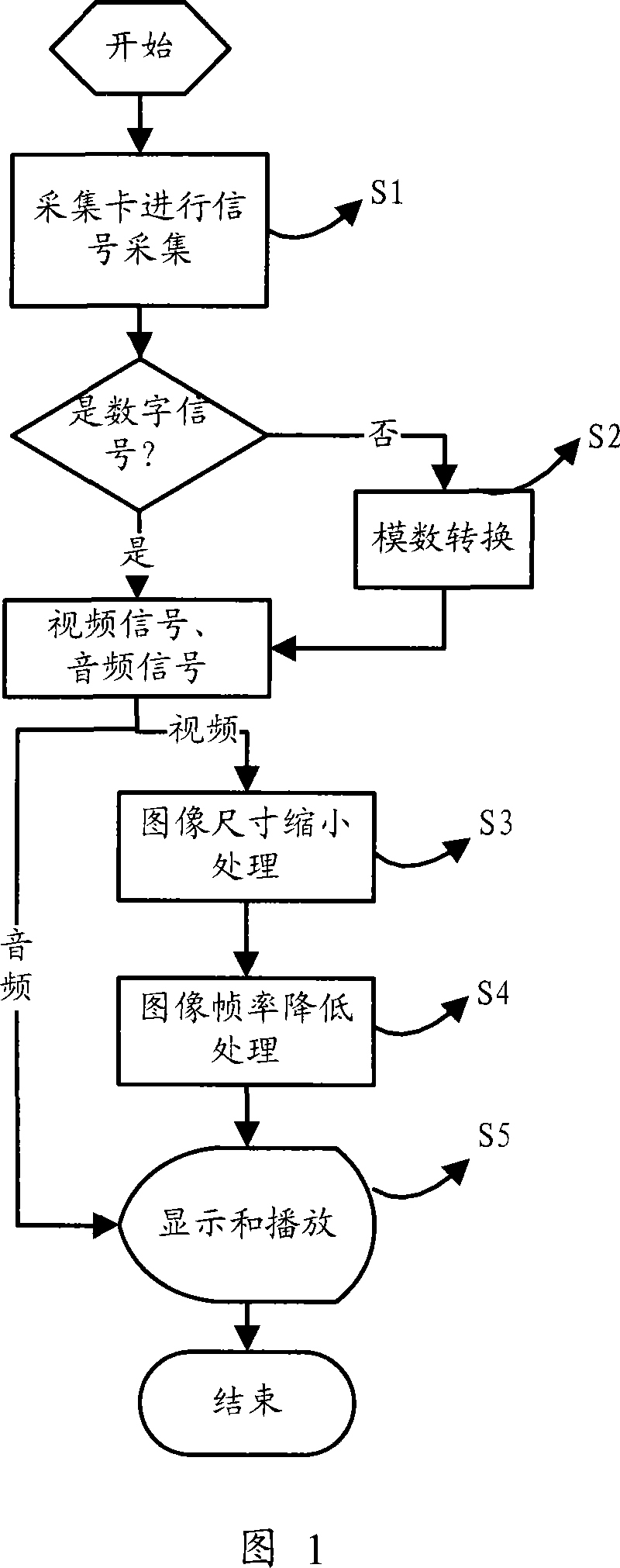
[0024] A signal real-time monitoring method of a coding device of the present invention, as shown in Figure 1, said method comprises the following steps:
[0025] S1. The encoding device collects audio and video input signals through the acquisition card, and the input signals include analog signals and digital signals;
[0026] S2. If the video signal collected in step S1 is an analog signal, then convert the analog signal into a digital signal for output; if the video signal collected in step S1 is a digital signal, then output the original signal;
[0027] S3. Perform size reduction processing on the large-size image formed by the video signal output in step S2 to form a small image;
[0028] S4. Perform frame rate reduction processing on the small image formed in step S3 to form an image with a low frame rate;
[0029] S5. Input the video signal and audio signal output in step S4 into the display device of the master control machine of the encoding device for real-time di...
Embodiment 2
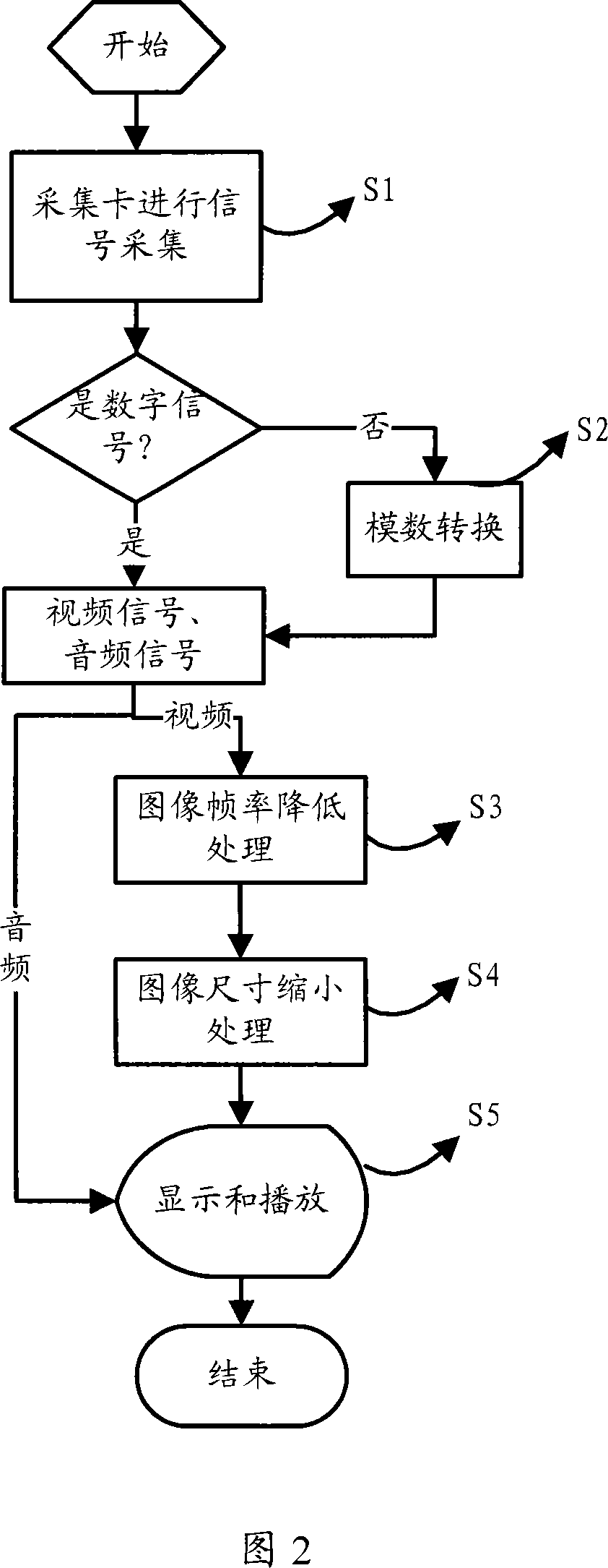
[0032] A signal real-time monitoring method of a coding device of the present invention, as shown in Figure 2, said method comprises the following steps:
[0033] S1. The encoding device collects audio and video input signals through the acquisition card, and the input signals include analog signals and digital signals;
[0034] S2. If the video signal collected in step S1 is an analog signal, the analog signal is converted into a digital signal for output; if the video signal collected in step S1 is a digital signal, the original signal is output;
[0035] S3. Perform frame rate reduction processing on the video signal output in step S2 to form a low frame rate image;
[0036] S4. Perform size reduction processing on the image formed in step S3 to form a small image;
[0037] S5. Input the video signal and audio signal output in step S4 into the display device of the master control machine of the encoding device for real-time display and playback, and the input and output si...
Embodiment 3
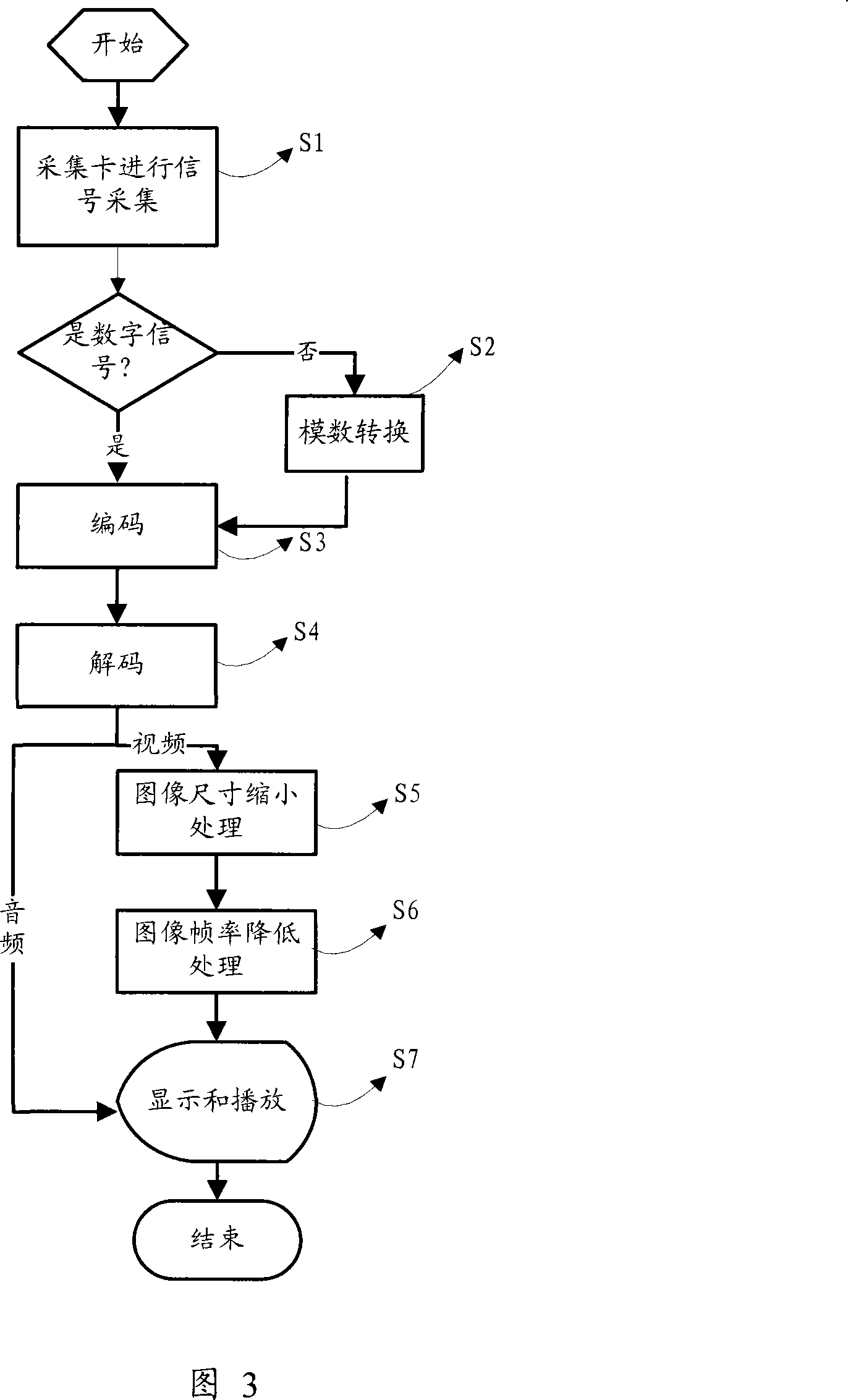
[0040] A signal real-time monitoring method of a coding device of the present invention, as shown in Figure 3, said method comprises the following steps:
[0041] S1. The encoding device collects audio and video input signals through the acquisition card, and the input signals include analog signals and digital signals;
[0042] S2. If the video signal collected in step S1 is an analog signal, then convert the analog signal into a digital signal for output; if the video signal collected in step S1 is a digital signal, then output the original signal;
[0043] S3, encoding the output signal of the acquisition card according to the encoding standard;
[0044] S4. Decoding the encoded video signal by a corresponding method and then outputting it;
[0045] S5. Reducing the size of the large-size image formed by the video signal output in step S4 to form a small image;
[0046] S6. Perform frame rate reduction processing on the small image formed in step S5 to form an image with ...
PUM
 Abstract
Description
Claims
Application Information