Full-movable push bar grate cooler

A grate cooler and pusher technology, which is applied in the field of fully movable pusher grate coolers, can solve the problems of complex structure and high energy consumption, and achieve the effects of good cooling effect, low power consumption and simple structure.

Inactive Publication Date: 2008-05-07
万大龙
View PDF0 Cites 12 Cited by
  • Summary
  • Abstract
  • Description
  • Claims
  • Application Information

AI Technical Summary

Problems solved by technology

[0003] The purpose of this invention is to design a fully movable push rod grate cooler for the proble

Method used


Image

  • Full-movable push bar grate cooler
  • Full-movable push bar grate cooler

Examples


Embodiment Construction

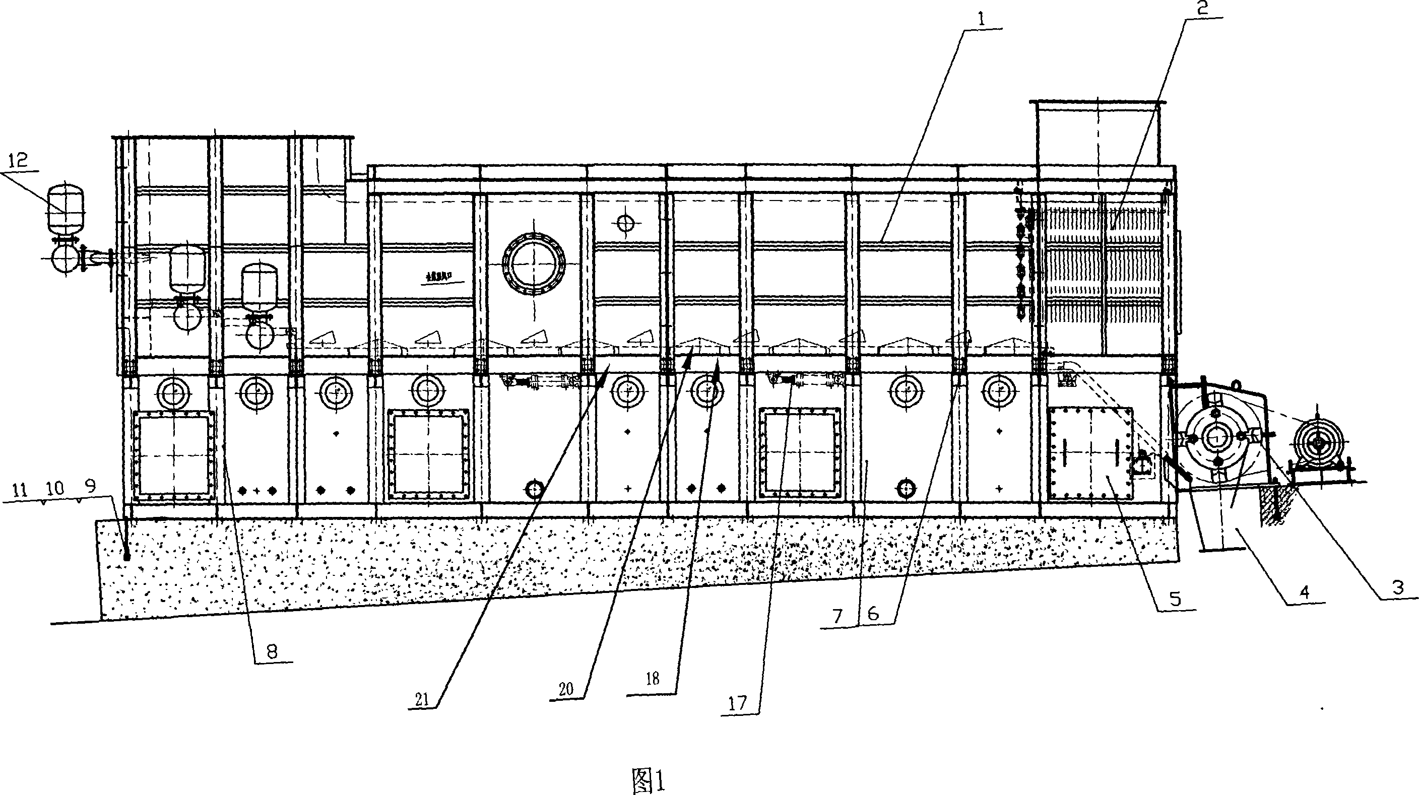
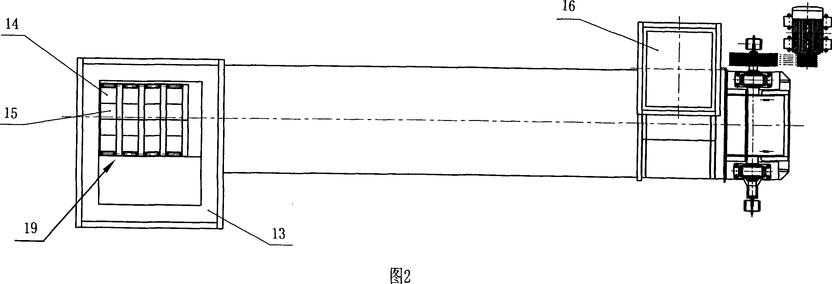
[0027] The following structural drawings and embodiments further illustrate the present invention.

[0028] As shown in Figure 1 and 2.

[0029] A fully movable push rod grate cooler, including a housing 1, a chain curtain device 2, a crusher 3, a standard module 8 at the feed end, a standard module 7 at the middle section, a standard module 5 at the discharge end, and a standard module 8 at the feed end Installed on one end of the housing 1, the chain curtain device 2, the crusher 3 and the discharge end standard module 5 are installed on the other end of the housing 1, the chain curtain device 2 is located on the upper part of the discharge end standard module 5, and the crusher 3 is located on the The outside of the discharge end standard module 5, the middle section standard module 7 is located in the housing 1, and the housing 1 is composed of the high temperature section adjacent to the feed end standard module 8, the low temperature section adjacent to the discharge end...


PUM


Abstract

The invention relates to a total-moving handspike grid cooling machine belonging to a cement furnace cooling device, and comprising a casing (1), a chain proscenia (2), a crusher (3), a feed end standard module (8), a middle segment standard module (7) and a discharge end standard module (5). The invention is characterized in that a fixed comb chilling bed (18) is arranged in the casing (1) and the top of the middle segment standard module (7). The feed end standard module (8) is provided with a step type fixed comb chilling bed (19) which has an air cannon (12). The comb chilling bed (18) is aslant arranged at the groundwork. A grid plate (20) forming the comb chilling bed (18) is arranged at a support beam (21) taking a wave line shape. The low point of the wave line is provided with a triangle moving feeding ram (6) which is connected with a driving oil cylinder (17) fixed at the support beam (21). The invention has the advantages of simple structure, convenient maintenance and long service life.

Description

technical field [0001] The invention relates to cement equipment, in particular to a cooling machine for rapid cooling of cement clinker, in particular to a fully movable push rod grate cooler. Background technique [0002] At present, it is well known that in cement production, the cooling rate of high-temperature clinker is one of the key measures affecting the quality of cement. In order to realize rapid cooling of high-temperature clinker, the existing high-temperature clinker cooling devices all adopt a grate bed structure. Internal forced air blowing to achieve rapid cooling. This kind of grate bed has the following problems. First, the structure is complex, and the motion control of the grate bed consumes a lot of energy, so the energy consumption is large; Small particles of clinker leak from between the bed boards into the air supply system. Therefore, a collecting hopper must be installed under the grate bed and a series of devices such as corresponding air lock ...

Claims


Application Information

Patent Timeline
IPC IPC(8): C04B7/47
Inventor 万大龙
Owner 万大龙
Why Eureka
Try Eureka