Fluorescent body coating method of fluorescent lamp

A technology for phosphors and fluorescent lamps, which is applied in the application of luminescent coatings, parts and coatings of gas discharge lamps, etc., can solve the problems of reducing production efficiency and increasing processes, so as to improve production efficiency, reduce equipment costs, and improve coating. The effect of the application process

Inactive Publication Date: 2008-05-07
WEIHAI DMS OPTICAL ELECTROMECHANICAL CO LTD
View PDF0 Cites 2 Cited by
  • Summary
  • Abstract
  • Description
  • Claims
  • Application Information

AI Technical Summary

Problems solved by technology

Therefore, the process is increase...

Method used


Image

  • Fluorescent body coating method of fluorescent lamp
  • Fluorescent body coating method of fluorescent lamp
  • Fluorescent body coating method of fluorescent lamp

Examples


Embodiment Construction

[0022] Hereinafter, preferred embodiments of the present invention will be described in detail with reference to the accompanying drawings.

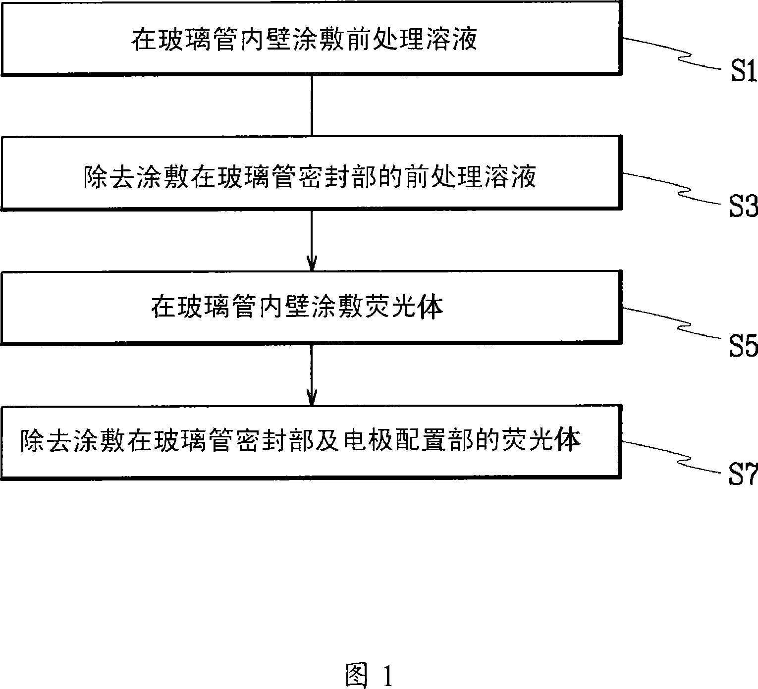
[0023] Figure 1 is a process flow diagram for illustrating an embodiment of the present invention. FIG. 1 sequentially shows a phosphor coating method for a fluorescent lamp. Fluorescent lamp phosphor coating method of the present invention, at first in glass tube 1 inner wall coating pretreatment solution, forms pretreatment solution layer (S1), utilizes isopropanol solution to remove the pretreatment solution that is coated on glass tube 1 sealing part afterwards layer (S3), and then apply phosphor on the inner wall of the glass tube (S5), and then use butyl acetate solution to remove the phosphor coated on the sealing part of the glass tube and the electrode arrangement part (S7).

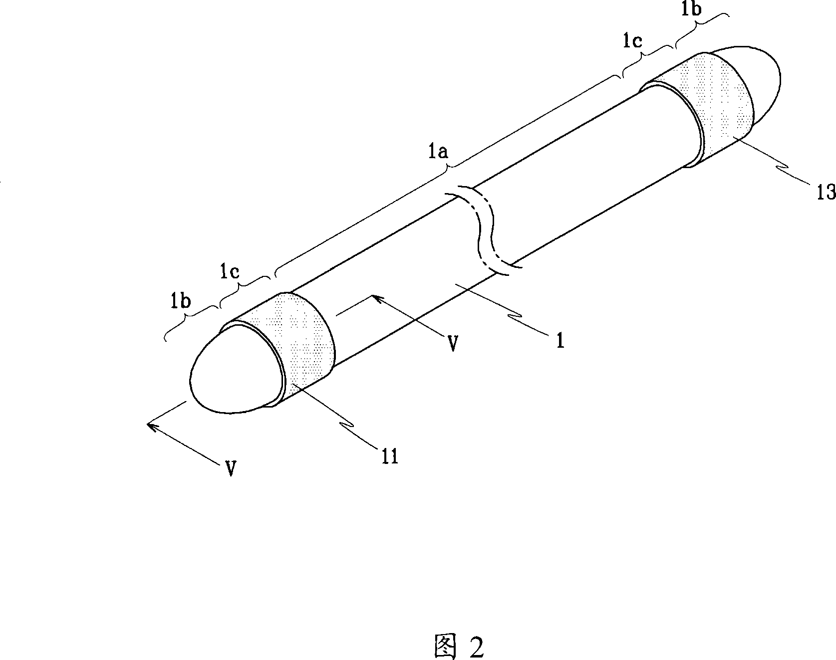
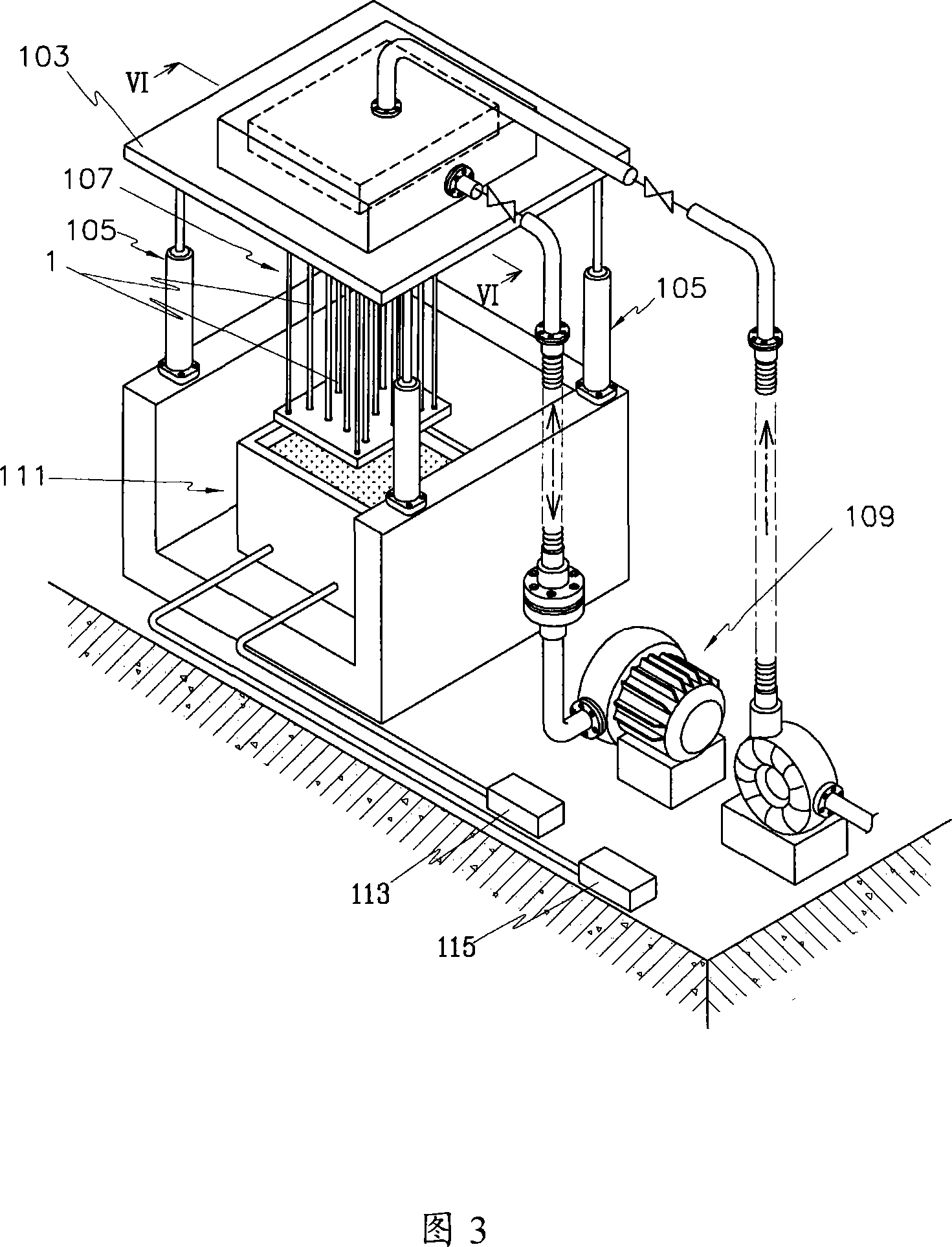
[0024] Fig. 2 is a perspective view illustrating the appearance and structure of a fluorescent lamp in an embodiment of the present invention, Fig. 3 is ...


PUM


Abstract

The invention relates to a fluophor coating method for a fluorescent lamp, in particular to a fluophor coating method which can reduce the operation procedures in the technique of manufacturing the fluorescent lamps through coating the fluophor in the fluorescent lamp. The invention includes the following procedures: treating a solvent before the coating to the inner wall of a glass tube; utilizing the solvent to clear a pre-treated solvent layer coated on a sealing part of the glass tube, after the treatment of the solvent before the coating; coating the inner wall of the glass tube with fluophors after the clearing o f the pre-treated solvent layer on the sealing part of the glass tube; utilizing the solvent to clear the fluophors adhered to the sealing part of the glass tube and an electrode arrangement part, after the coating of the fluophors.

Description

technical field [0001] The present invention relates to a fluorescent substance coating method of a fluorescent lamp, in particular to a fluorescent substance coating method of a fluorescent lamp which can reduce working procedures in the manufacturing process of coating a fluorescent substance for a fluorescent lamp. Background technique [0002] Generally, fluorescent lamps are classified into cold cathode fluorescent lamps (CCFL: Cold Cathode Fluorescent Lamp) and external electrode fluorescent lamps (EEFL: External Electrode Fluorescent Lamp). These fluorescent lamps are manufactured by injecting gas and mercury after exhausting the gas inside the glass tube for fluorescent lamps, and then sealing it to a certain size. That is, a fluorescent lamp has a certain amount of argon gas and mercury enclosed in a state where a phosphor is coated inside a glass tube, and two electrodes are provided inside or outside of both ends of the sealed glass tube. Phosphor acts to excite ...

Claims


Application Information

Patent Timeline
IPC IPC(8): H01J9/22H01J9/20B05C9/08B05D3/00
CPCH01J9/22H01J61/42H01J2209/012H01J2209/017
Inventor 李永哲崔起硕
Owner WEIHAI DMS OPTICAL ELECTROMECHANICAL CO LTD
Why Eureka
Try Eureka