Ultrasonographic device and ultrasonic elastic image acquisition method

A technology of elastic image and diagnostic device, which is applied in the directions of ultrasonic/sonic/infrasonic image/data processing, acoustic diagnosis, infrasonic diagnosis, etc., and can solve problems such as inability to use image information flexibly

Inactive Publication Date: 2008-05-07
HITACHI MEDICAL CORP
View PDF1 Cites 20 Cited by
  • Summary
  • Abstract
  • Description
  • Claims
  • Application Information

AI Technical Summary

Problems solved by technology

[0008] However, as disclosed in the patent literature, in the method of obtaining elasticity information by using the maximum value of the deformation amount or the maximum value and minimum value of the artery diameter to visualize the elasticity image, the elasticity image of the blood vessel wall is often only intermittent. Therefore, effective image information cannot be fully utilized in diagnosis

Method used


Image

  • Ultrasonographic device and ultrasonic elastic image acquisition method
  • Ultrasonographic device and ultrasonic elastic image acquisition method
  • Ultrasonographic device and ultrasonic elastic image acquisition method

Examples


no. 1 approach

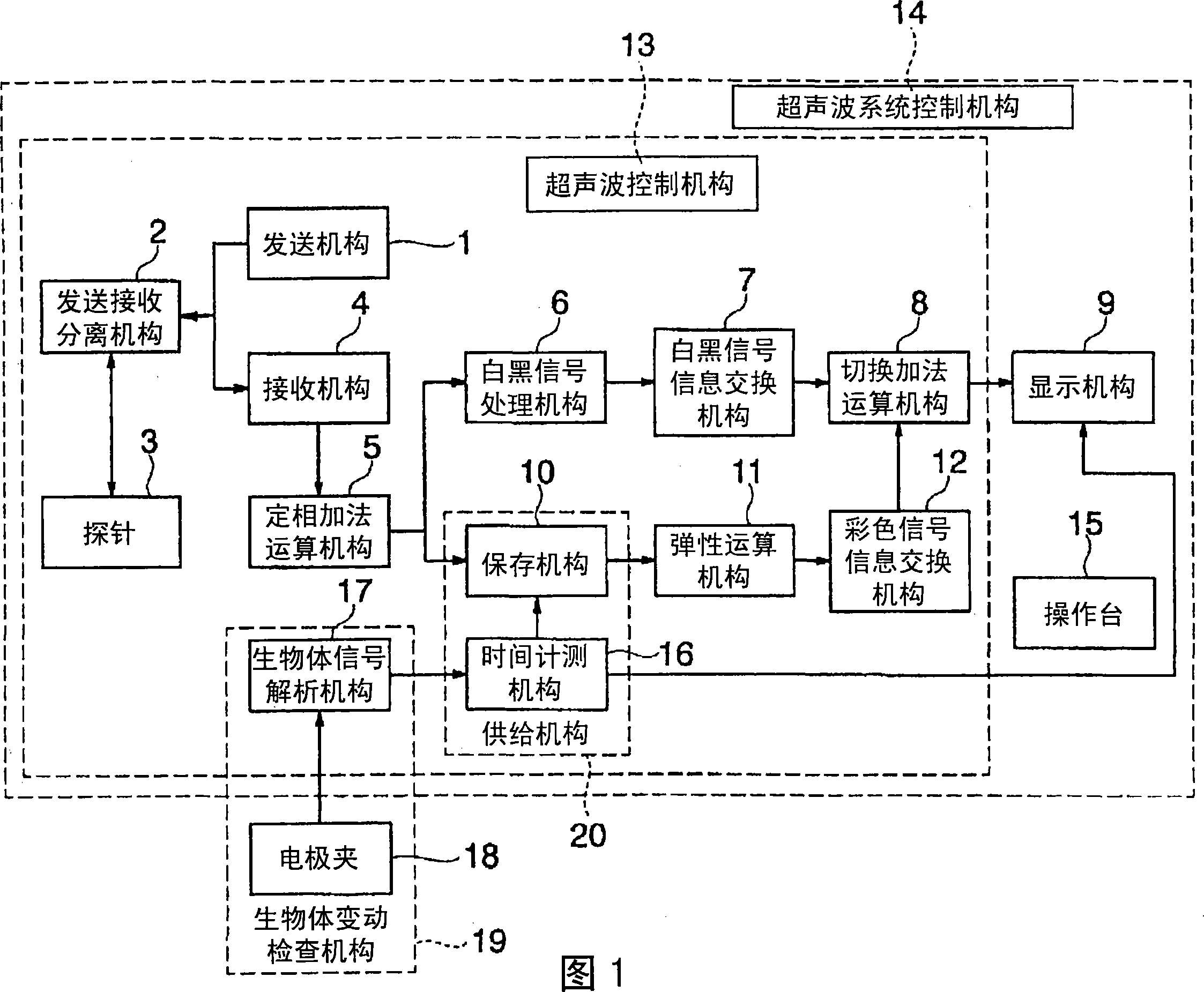
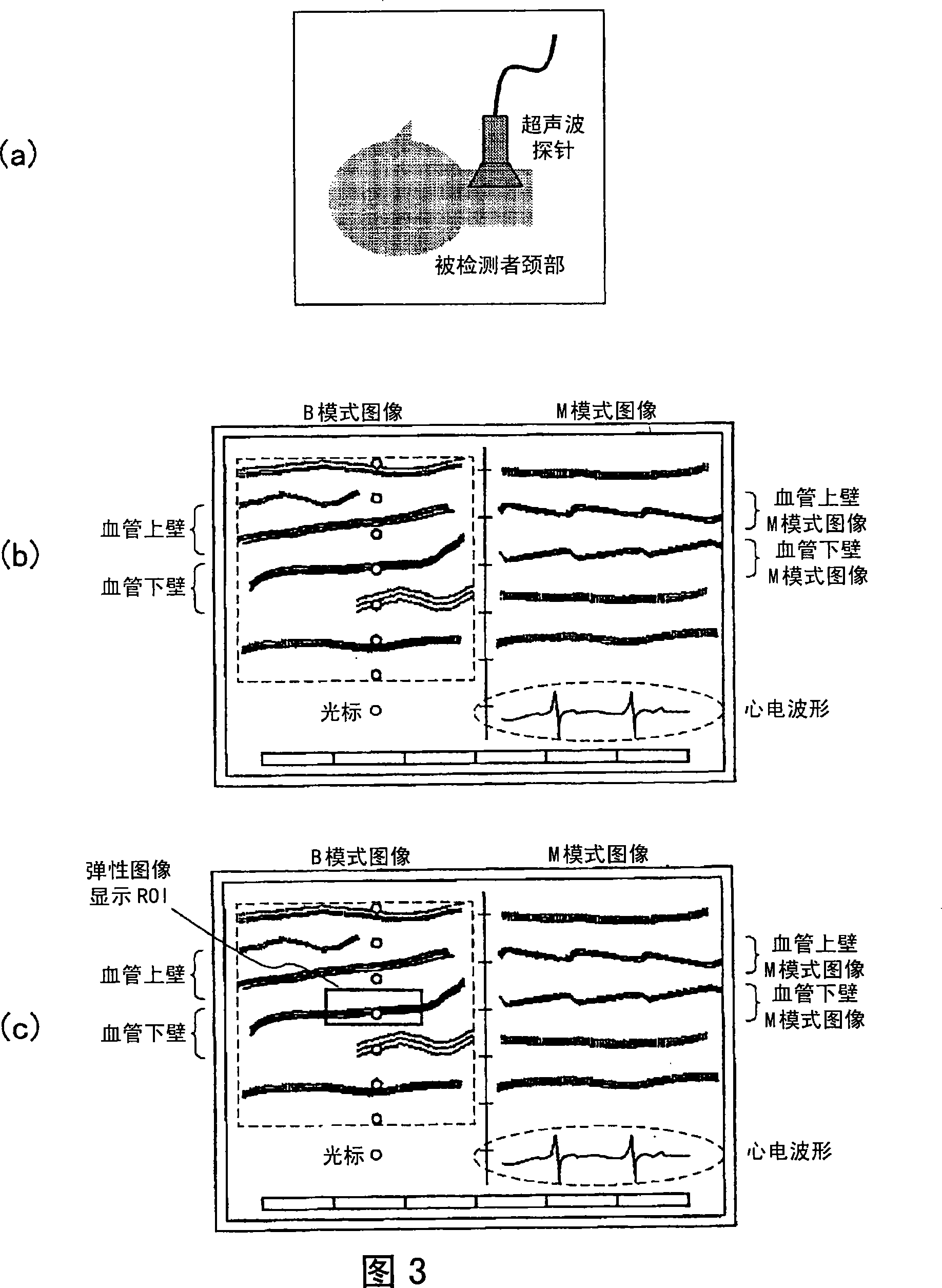
[0059] Next, a first embodiment of the present invention will be described. In this embodiment, the selection of the acquisition period of the elasticity image and the control of the acquisition frequency are performed according to the displacement of the blood vessel wall caused by the beating of the heart. The displacement of the blood vessel wall is detected, for example, by using an M-mode image.

[0060] First, the time measuring means 16 and the biological signal analyzing means 17 constituting the living body change checking means 19 will be described.

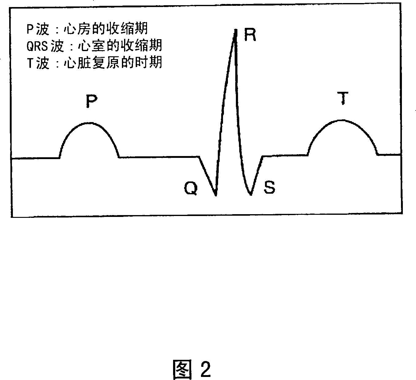
[0061] The biological signal analysis means 17 has a function of taking in biological signals generated in the subject and displaying them as electrocardiographic waveforms by the display means 9 . In general, when measuring an electrocardiogram, the electrode clip 18 is placed on the wrist and ankle of the subject for measurement, and the changes in the great vein called the sinoatrial node of the myocardium are recor...

no. 2 approach

[0111] Next, a second embodiment of the present invention will be described. The present embodiment is a mode in which selection of an elastic image acquisition period and control of acquisition frequency are performed according to the amount of displacement of internal thoracic and abdominal tissues caused by breathing motion. The amount of displacement of tissues in the chest and abdomen is detected using, for example, tomographic image (B-mode image) data. The difference from the above-mentioned first embodiment is the displacement amount detection method based on the type of body movement of the subject and the specific elastic image acquisition control, and the others are the same. Hereinafter, only the different parts will be described, and the description of the same parts will be omitted. In addition, the present embodiment can also be implemented in either the real-time mode or the freeze mode.

[0112] As an example of this embodiment, an example of acquiring an el...


PUM


Abstract

[Problem] To select a period suitable for acquiring an elastic image in accordance with variation of the displacement amount of a moving tissue when the elastic image of the moving tissue is acquired, thereby stably acquiring an elastic image of high image quality. [Means for Resolution] A ultrasonic diagnostic apparatus including an ultrasonic probe for transmitting / receiving ultrasonic waves to / from a site containing a moving tissue of an examinee, ultrasonic wave transmitting means for outputting an ultrasonic wave signal for driving the ultrasonic probe, morphological image acquiring means for acquiring a morphological image representing morphological information of the site containing the moving tissue from a reflected echo signal received by the ultrasonic probe, elastic image acquiring means for acquiring an elastic image representing elastic information of the site containing the moving tissue by using a plurality of morphological image data, displacement amount detecting means for detecting a displacement amount of the moving tissue by using the morphological image data, and selecting means for selecting an elastic image acquiring period on the basis of the displacement amount, wherein the elastic image acquiring means acquires an elastic image during the selected period.

Description

technical field [0001] The present invention relates to an ultrasonic diagnostic apparatus for obtaining a tomographic image of a diagnostic part in a subject using ultrasonic waves, and more particularly to a technique for obtaining an elastic image indicating the hardness or softness of a diagnostic part. Background technique [0002] A conventional ultrasonic diagnostic apparatus is provided with an ultrasonic transceiver mechanism for sending and receiving (transmitting and receiving) ultrasonic waves to a subject, and repeatedly acquires the detected object including moving tissue at a predetermined cycle using the reflected echo signal received by the ultrasonic transceiver mechanism. A tomographic image acquisition unit for in-vivo tomographic image data and an image display unit for displaying time-series tomographic images acquired by the tomographic image acquisition unit are configured. Furthermore, it is configured to display the form information of the living ti...

Claims


Application Information

Patent Timeline
Patent Type & Authority Applications(China)
IPC IPC(8): A61B8/08
CPCA61B8/14A61B8/13A61B8/06A61B8/485A61B8/0858A61B8/543
Inventor 大坂卓司村山直之
Owner HITACHI MEDICAL CORP
Why Eureka
Try Eureka