Brake control device for elevator

A brake control and elevator technology, which is applied in hoisting devices, transportation and packaging, elevators, etc., can solve the problem of not using two windings to continuously control the winding current

Inactive Publication Date: 2008-05-14
HITACHI LTD +1
View PDF8 Cites 10 Cited by
  • Summary
  • Abstract
  • Description
  • Claims
  • Application Information

AI Technical Summary

Problems solved by technology

[0026] In addition, the elevator brake device proposed in Patent Document 8 adopts a structure in which a plurality of windings are used for the electromagnet. The method is to divide the plurality of windings into a winding used in

Method used


Image

  • Brake control device for elevator
  • Brake control device for elevator
  • Brake control device for elevator

Examples


Embodiment Construction

[0137] Embodiments of the present invention will be described below with reference to the drawings.

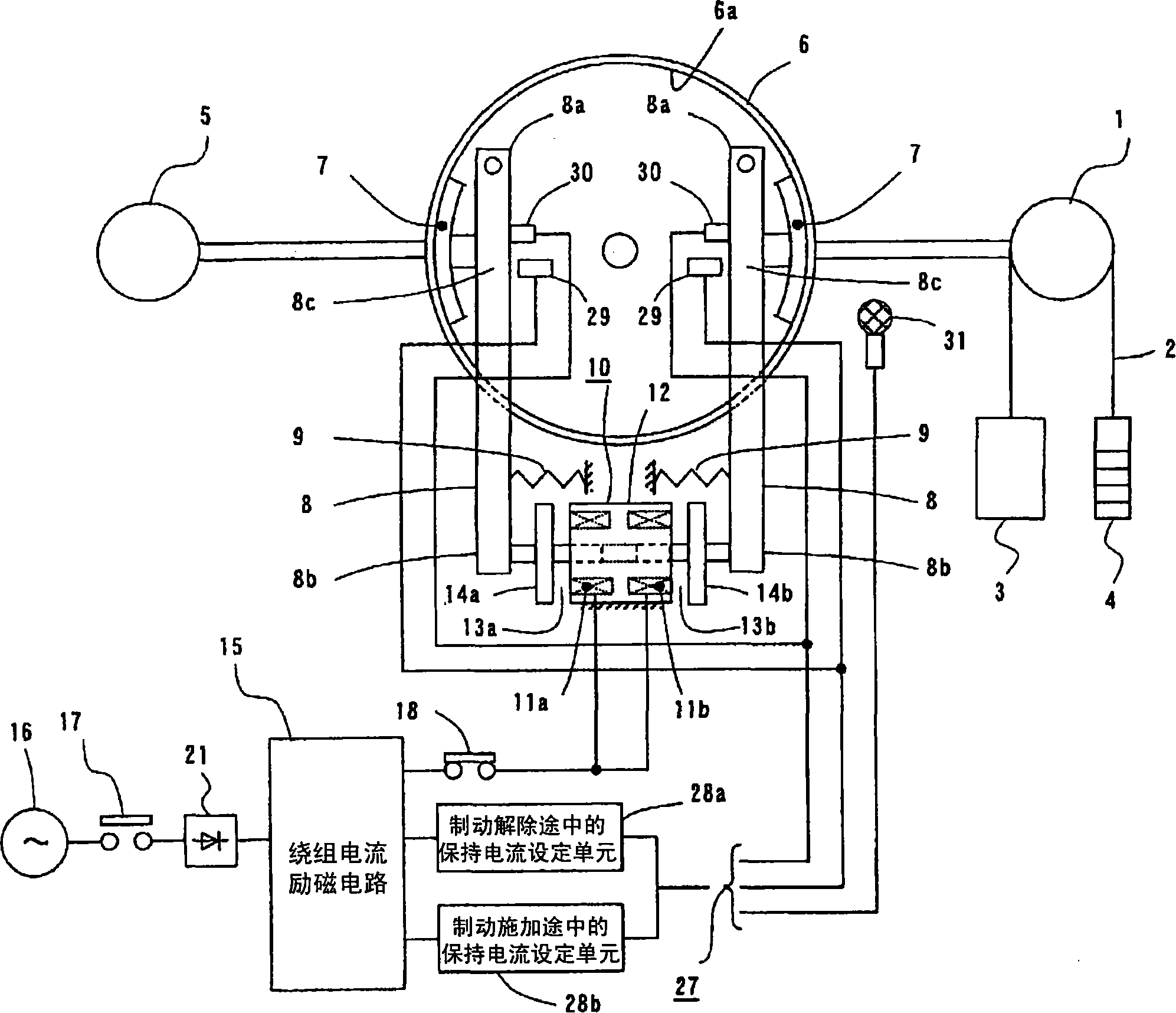
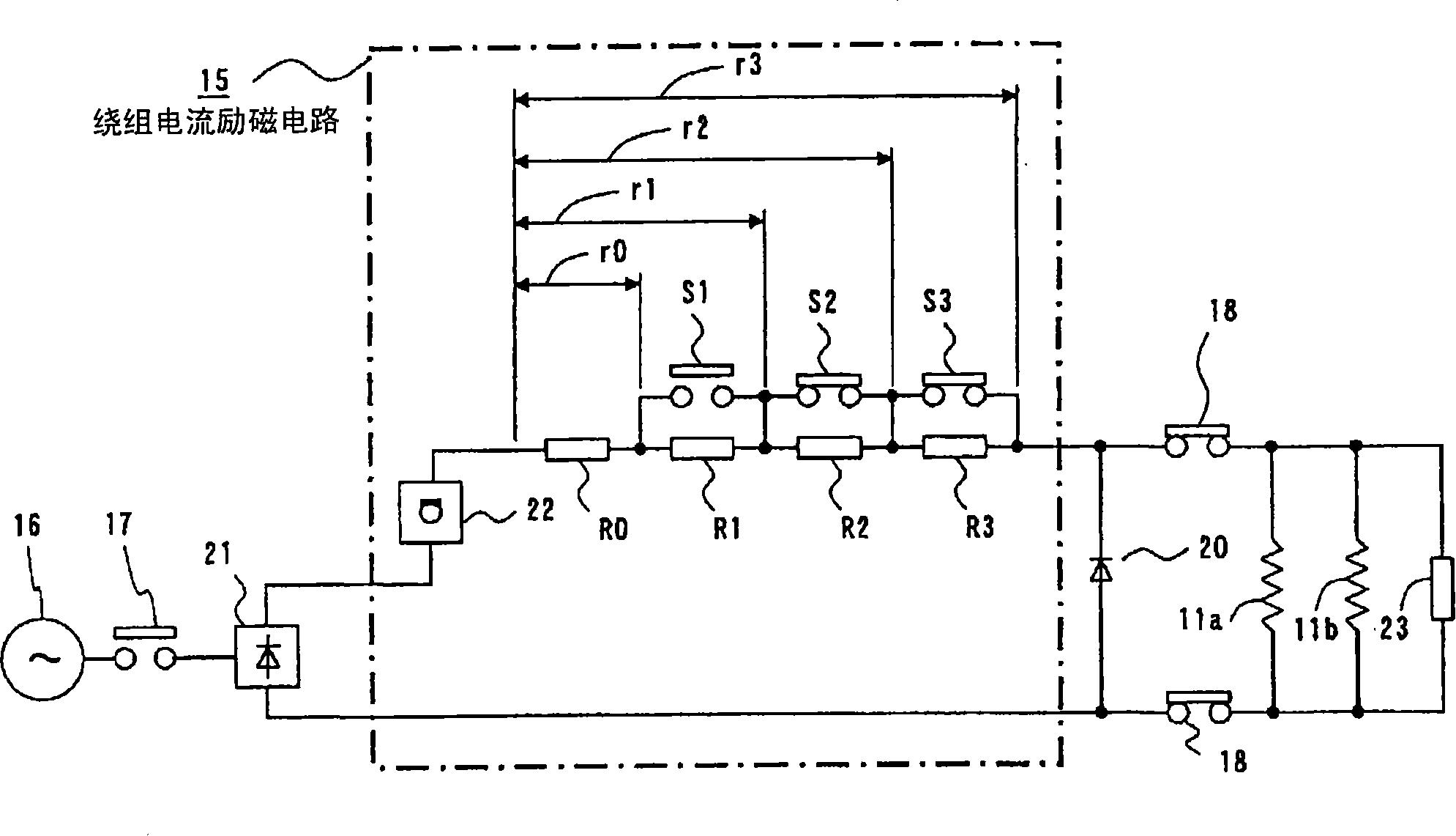
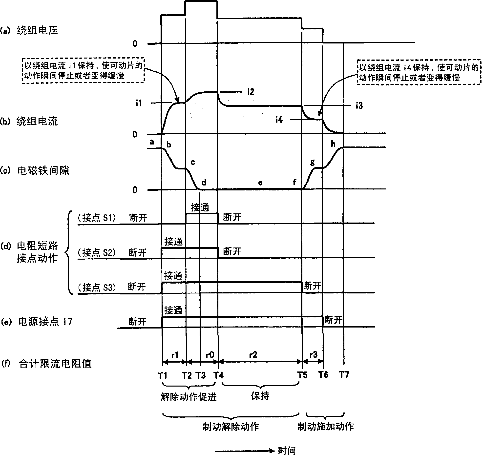
[0138] Figure 1 to Figure 4 One embodiment of the brake control device for elevators according to the present invention is shown. figure 1 It is the overall structure diagram of the brake control device for elevators, figure 2 Yes figure 1 The excitation circuit of the electromagnetic winding, image 3 is a timing chart showing the brake operation, Figure 4 Indicates the relationship between the winding current and the electromagnet gap, especially the image 3 The holding position of the winding current when the brake is released and when the brake is applied. Figure 5 to Figure 7 It is an illustration diagram of the winding voltage and current pattern when the brake is released or when the brake is applied.

[0139] exist figure 1 Among them, 1 represents the sheave of the hoisting machine, and the elevator car 3 is suspended on one side of the main rope 2 woun...


PUM


Abstract

The utility model discloses a brake control device for elevator, which doesn't produce any action lagging when rescinding the brake, and doesn't need gradually increase the control of the winding current when braking, so the invention can reduce the collision sound of the brake. In the brake control device for elevator, when the brake is rescinded, the winding current is controlled by any one current in stepped currents of one to three steps; when the brake is being applied, the winding current is controlled by the stepped current of one to two steps.

Description

technical field [0001] The invention relates to a braking control device for an elevator that obtains braking force by pressing a brake pad against a brake drum. Background technique [0002] Conventionally, there is known a brake control device for an elevator that obtains a braking force by pressing a brake shoe against a brake drum. For example, in the brake control devices for elevators disclosed in Patent Documents 1 to 5, when the brake is released or the brake is applied, or during the time period from the brake release to the brake application, the electromagnetic winding is activated according to the command. (DC electromagnet) is energized or disconnected to drive the brake pad integrally formed with the movable piece. [0003] In addition, for example, Patent Document 6 proposes a scheme for adjusting a DC power supply. [0004] Also, for example, Patent Document 7 and Patent Document 8 propose using a plurality of windings. [0005] Patent Document 1 Japanese ...

Claims


Application Information

Patent Timeline
IPC IPC(8): B66D5/08B66D5/30B66B1/32
Inventor 伊藤正信五十岚章智松浦厚
Owner HITACHI LTD
Why Eureka
Try Eureka