
Plasma display device

A technology for plasma and display devices, applied in identification devices, optical/shielding devices, static indicators, etc., can solve problems such as EMI noise and increase cost

Inactive Publication Date: 2008-05-14
SAMSUNG SDI CO LTD
View PDF0 Cites 1 Cited by
  • Summary
  • Abstract
  • Description
  • Claims
  • Application Information

AI Technical Summary

Problems solved by technology

Potential for EMI noise and increased cost due to increased part count

Method used


Image

  • Plasma display device
  • Plasma display device
  • Plasma display device

Examples


Embodiment Construction

[0022] Some embodiments are now described with reference to the figures. As those skilled in the art would realize, the described embodiments may be modified in various different ways, all without departing from the spirit or scope of the present invention.

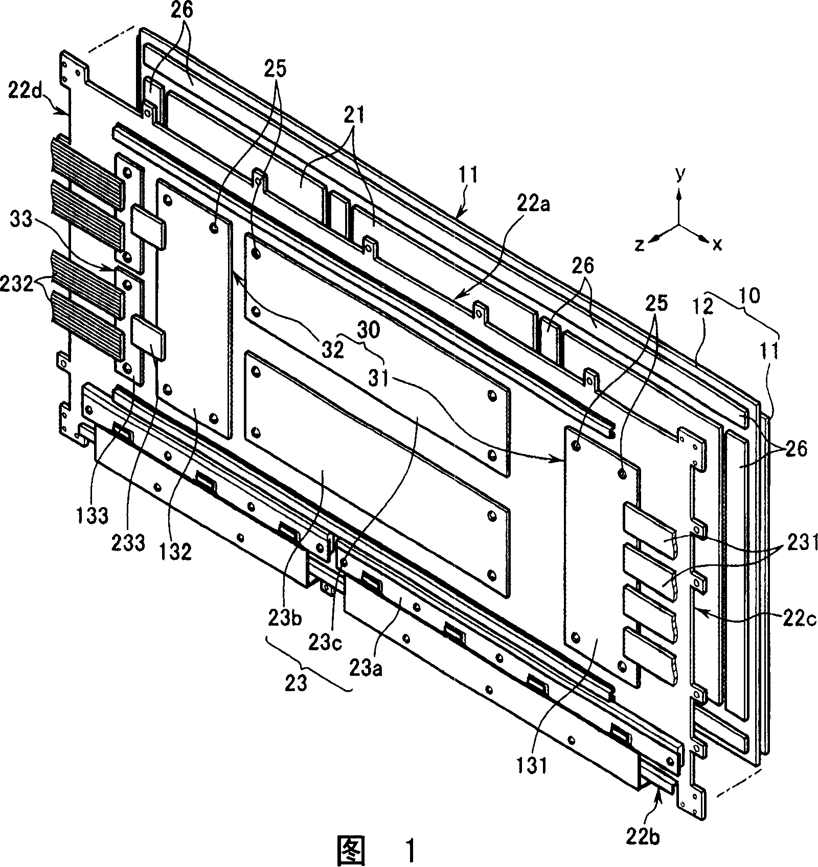
[0023] FIG. 1 is an exploded perspective view schematically showing a plasma display device. 1, the plasma display device includes: a plasma display panel 10 for displaying images by gas discharge, a heat sink 21, a chassis base 22, a printed circuit board 23, and a partially rigid and partially flexible printed circuit board 30.

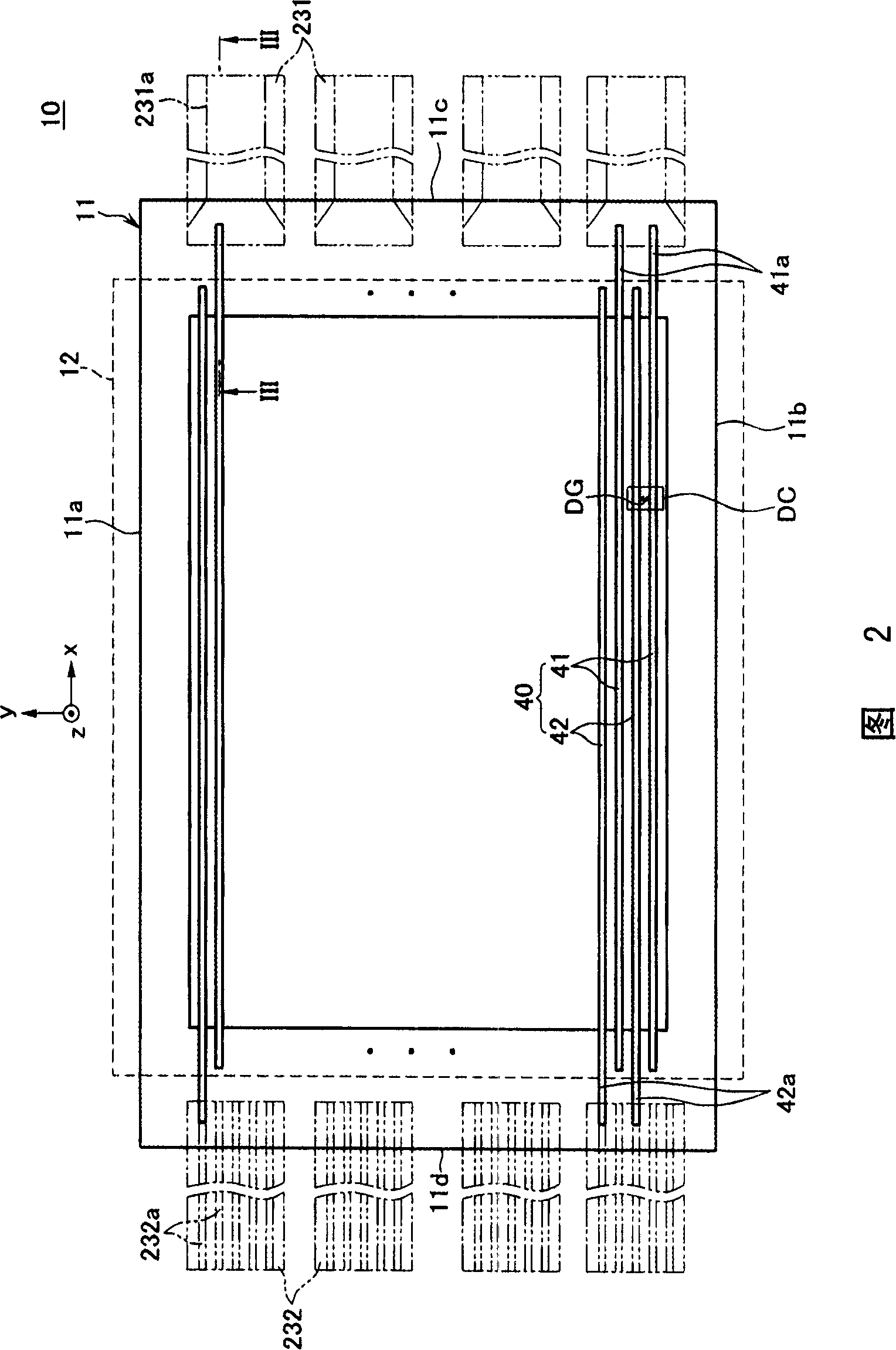
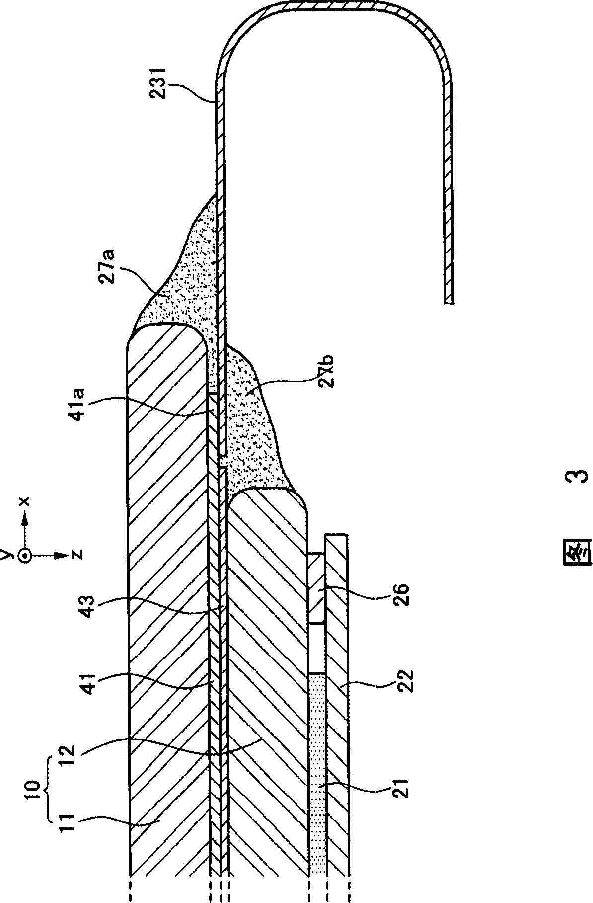
[0024] The plasma display panel 10 is formed by encapsulating two substrates, for example, a front substrate 11 and a rear substrate 12 spaced apart from each other by a certain distance. Referring to FIG. 2, the plasma display panel 10 is generally rectangular, having two facing long sides and two facing short sides substantially perpendicular to the long sides in the xy plane. The rear sub...


PUM


Abstract

A plasma display device having improved connection reliability between display electrodes of a plasma display panel and printed circuit boards, thereby reducing electromagnetic interference (EMI) noise, and reducing cost due to reduction of the number of components is disclosed. The plasma display device includes a partly rigid and partly flexible printed circuit board which is mounted on the chassis base and is connected to display electrodes of the plasma display panel.

Description

technical field [0001] The present invention relates to a plasma display device, and more particularly, to a method capable of improving the connection between the display electrode and the partially rigid and partially flexible printed circuit board by connecting the partially rigid and partially flexible printed circuit board to the display electrode of the plasma display panel. A plasma display device with connection reliability between flexible printed circuit boards, thereby reducing electromagnetic interference (EMI) noise, and reducing cost due to reduced number of parts. Background technique [0002] Generally, a plasma display device includes a plasma display panel for displaying images, a chassis base fixed to the plasma display panel to support the plasma display panel, and a chassis base mounted on the chassis base and electrically connected to the plasma display panel. Multiple printed circuit boards for bulk display panels. [0003] The plasma display panel ge...

Claims


Application Information

Patent Timeline
Patent Type & Authority Applications(China)
IPC IPC(8): G09F9/313H01J17/49G09G3/28H05K1/02H05K1/11
CPCH05K5/02H05K1/147H01J11/44H01J11/46
Inventor 郑武一
Owner SAMSUNG SDI CO LTD
Learn More