
Pallet for conveying monolithic plate

A single-piece board and pallet technology, which is applied to conveyors, conveyor objects, transportation and packaging, etc., can solve the problems of large conflict impact of pallet 101, damage to workpiece 112, damage to workpiece 112, etc., so as to reduce costs and restrain individual components. The effect of increasing the number, eliminating position shift and breakage

Inactive Publication Date: 2008-05-21
MURATA MASCH LTD
View PDF2 Cites 8 Cited by
  • Summary
  • Abstract
  • Description
  • Claims
  • Application Information

AI Technical Summary

Problems solved by technology

That is, when the tray 101 is transferred from the upstream conveyor 120a to the downstream conveyor 120b, when the height position of the conveying rollers 121 of the downstream conveyor 120b is slightly higher than the height position of the upstream conveyor 120a, The end 110a of the flange wall 110 located at the leading end side in the transport direction of the tray 101 may collide with the upstream transport roller 121a of the downstream conveyor 120b, thereby applying a large collision impact to the tray 101.
Alternatively, when the two conveyors 120a and 120b are separated by a predetermined distance or more, the height of the end portion 110a becomes lower than the conveying surface due to the self-weight of the pallet 101 and the workpiece 112, and the pallet 101 deflects. May conflict with delivery roller 121a
In this way, when a large collision impact is applied to the pallet 101, the pallet 101 and the workpiece 112 vibrate, and the workpiece 112 placed on the mullions 105 may be shifted in the pallet 101, or the workpiece 112 may be damaged in the worst case.
In particular, when the workpiece 112 is a glass substrate of a large liquid crystal television, it is easy to damage the workpiece 112 only by applying a slight vibration.
Also, since the end 110a of the flange wall 110 collides with the conveying roller 121a, the conveying roller 121a may be damaged to generate particles, which is problematic especially when conveying in an environment requiring the cleanliness of the tray 101

Method used


Image

  • Pallet for conveying monolithic plate
  • Pallet for conveying monolithic plate
  • Pallet for conveying monolithic plate

Examples


Embodiment Construction

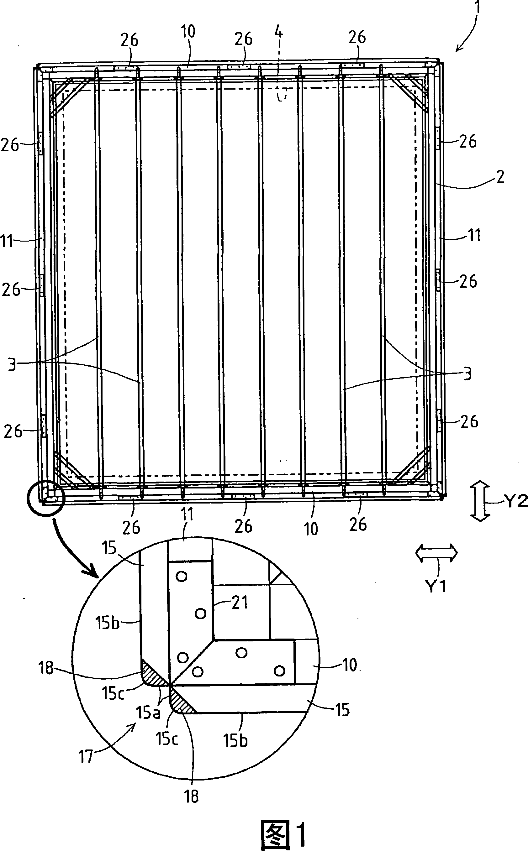
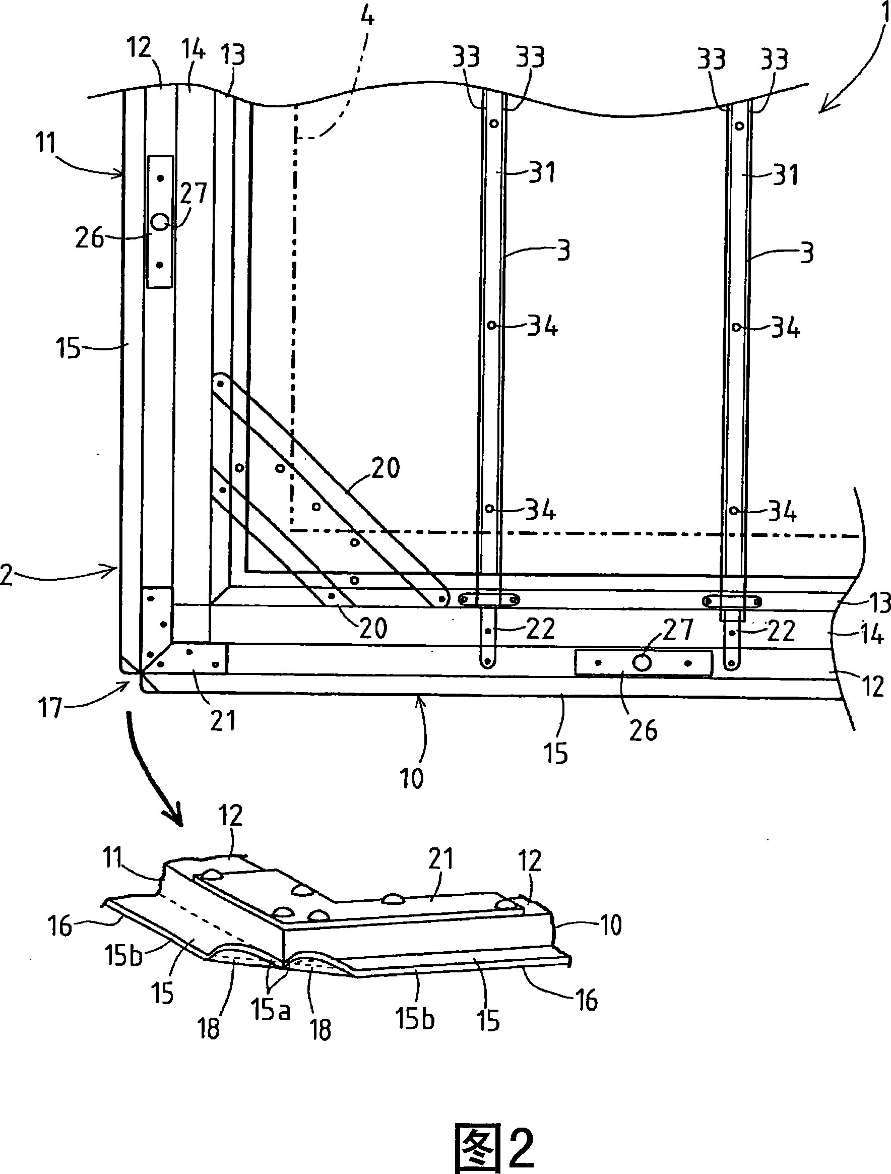
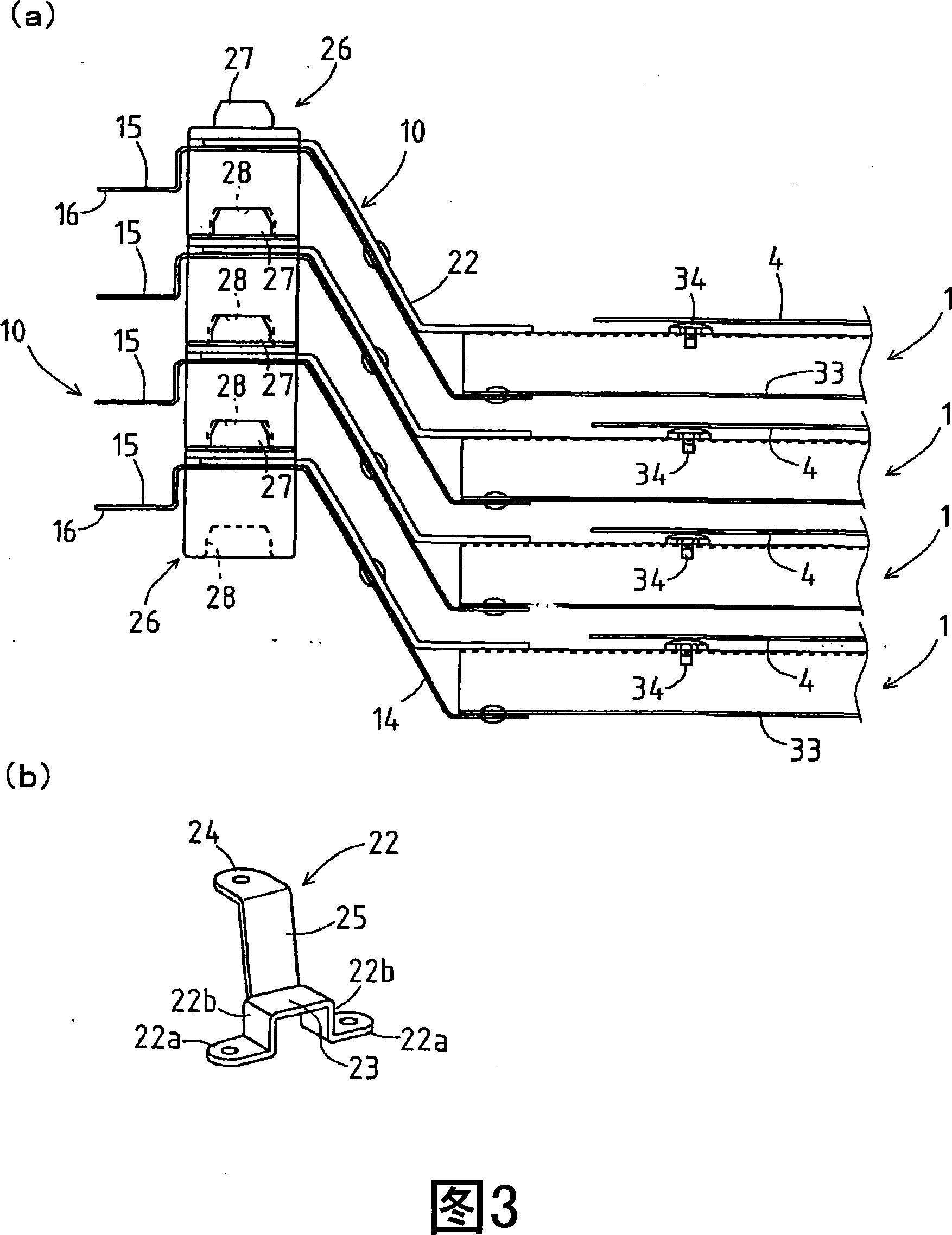
[0026] Hereinafter, embodiment of the tray for sheet|seat board conveyance which concerns on this invention is demonstrated, referring drawings. Fig. 1 is a plan view showing the overall structure of the single-sheet conveying tray of the present invention, Fig. 2 is an enlarged view of important parts, Fig. 3 is a view showing a state in which trays are stacked, and Figs. 4 to 6 show roller conveyance. A diagram of the conveying state of the single-piece board conveying tray of the machine. In addition, in FIG. 1 , the following is specified: the direction indicated by the arrow Y1 is the front-rear direction, and the direction (arrow Y2 ) orthogonal to this direction is the left-right direction.

[0027] As shown in FIG. 1 , a pallet (hereinafter referred to simply as "tray") 1 for conveying single-piece boards has a hollow quadrangular frame-shaped outer frame 2 and a plurality of (in this paper) erected between the left and right sides of the outer frame 2. In the embodim...


PUM


Abstract

The invention provides a single-web plate transporting pallet without large clash impact stressed on even when moving between two roller transporters, thereby eliminating the bad influences such as impact and rotation so as to transport work pieces smoothly. An inclined side (18) which faces towards to the transportation direction and inclines upwards is formed at the front end of the transportation direction side of a roller support side (16) which is bore by a transportation roller (6). Therefore, when the pallet (1) is moved at the discontinuous position of the transportation side in a manner of moving between the two transporters (5, 5), the inclined side (18) is firstly contacted with the transportation roller (6), thereby getting over the transportation roller (6) through the inclined side (18) so as to effectively baffle the clash impact on the pallet (1) and to smoothly move the pallet (1). Therefore, the invention can reliably eliminate the bad influences such as position displacement and damage of the work pieces (4) caused by the clash impact and vibration of the pallet (1).

Description

technical field [0001] The present invention relates to a pallet for conveying single-piece boards, which has a quadrangular frame-shaped outer frame conveyed by a conveyor and a plurality of mullion bars erected between opposite sides of the outer frame, and the upper surfaces of these mullion bars are used as The loading surface of single-chip workpieces. Background technique [0002] The so-called single-sheet (leaf) conveying tray is a plate-like object represented by a glass substrate of a thin display device as a conveying target (for example, Patent Document 1). A conventional form of such a tray for single-sheet conveyance is shown in FIG. 8 and FIG. 9 (refer to Japanese Patent Application No. 2005-214159 of the present applicant). In FIG. 8 , the outer frame 102 constituting the tray 101 is assembled into a quadrangular frame by two frames 103, 103 extending in the front-rear direction (arrow Y1) and two frames 104, 104 extending in the left-right direction (arrow ...

Claims


Application Information

Patent Timeline
Patent Type & Authority Applications(China)
IPC IPC(8): B65D6/04B65D21/032B65D85/48B65G13/00B65G49/06
CPCB65G17/24B65G47/54B65G49/063B65G2201/0258B65G2207/28
Inventor 中西秀明
Owner MURATA MASCH LTD
Learn More