Improvement to a fuel-injection system for an internal-combustion engine

A fuel injection system and the technology of the injection system, which are applied in the directions of fuel injection pump, fuel injection device, low-pressure fuel injection, etc., can solve the problems of interference and delay of the restart effect of solenoid valve, etc.

Inactive Publication Date: 2008-05-21
CENT RICERCHE FIAT SCPA
View PDF0 Cites 7 Cited by
  • Summary
  • Abstract
  • Description
  • Claims
  • Application Information

AI Technical Summary

Problems solved by technology

When the solenoid valve is opened again, the fuel flow in the pipe section must start flowing again from standst

Method used


Image

  • Improvement to a fuel-injection system for an internal-combustion engine
  • Improvement to a fuel-injection system for an internal-combustion engine

Examples


Embodiment Construction

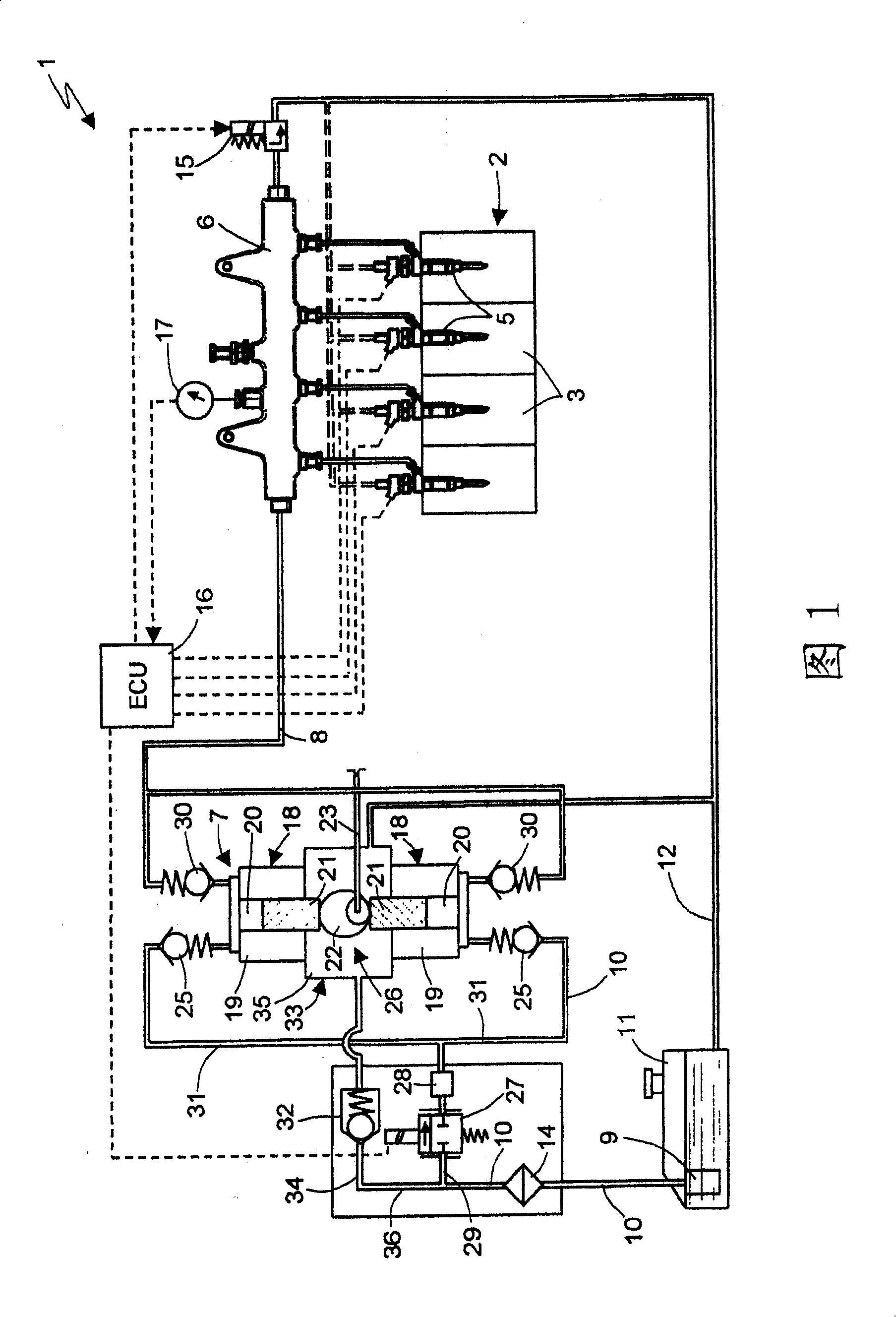
[0011] Referring to FIG. 1 , the entire fuel injection system for an internal combustion engine (which may be, for example, a four-stroke diesel engine) 2 is indicated by the reference numeral 1 . The internal combustion engine 2 includes a plurality of cylinders 3, for example four cylinders. The injection system 1 comprises a plurality of electronically controlled injectors 5 associated with the cylinders 3 , these injectors 5 being designed to inject high pressure fuel into the cylinders 3 . The injectors 5 are connected to an accumulation volume of pressurized fuel, which is formed, for example, by a common common rail 6 to which all the injectors 5 are connected.

[0012] The common rail 6 is supplied with high-pressure fuel via an oil outlet pipe 8 by a high-pressure pump, generally designated by the reference numeral 7 . In turn, the high pressure pump 7 is supplied by a low pressure pump (eg, the electric pump 9 ) through the oil inlet pipe 10 of the pump 7 . The ele...


PUM


Abstract

The invention provides an injection system comprising a high-pressure pump (7) with a variable flow rate, the high-pressure pump having at least one pumping element (18) provided with a An oil inlet valve (25) and an oil outlet valve (30) communicated with the oil outlet pipe (8). A pressure regulator (32) is provided on the oil inlet line (10) downstream of a metering solenoid valve (27) designed to meter the flow of the pump (7) according to the operating conditions of the internal combustion engine. The pressure regulator (32) is designed to vent excess fuel into the chamber (35) of the crankcase (33) to lubricate the usual actuating structure (26) of the pumping element. Between the inlet (29) of the solenoid valve (27) and the inlet (34) of the pressure regulator (32) there is a control volume (37) designed to accommodate a quantity of fuel that The amount ensures sufficient fuel flow in the area corresponding to the inlet (29) of the solenoid valve (27).

Description

technical field [0001] The present invention relates to improvements in fuel injection systems for internal combustion engines comprising a high pressure pump with variable delivery or flow, the high pressure pump having at least one pumping element actuated in reciprocating motion. Background technique [0002] In known high-pressure pumps of the type described above, the flow rate of the pump has to be adjusted according to the operating conditions of the internal combustion engine in order to prevent the delivery of too much fuel to the common common rail used to supply the injectors and in this way reduce the The work absorbed by the high pressure pump. In general, pumps of the type described above are supplied with fuel by means of a low-pressure pump, which for economical reasons is usually an electric pump supplied with a constant voltage and thus delivers a constant flow of fuel. The capacity of the electric pump is such that the constant flow delivered is equal to ...

Claims


Application Information

Patent Timeline
IPC IPC(8): F02M63/02F02M59/34F02M59/44
CPCF02M37/00F02M63/0265F02M63/023F02M53/00F02M63/0225F02M59/366F02M63/0001F02M55/02F02M69/00
Inventor 马里奥·里科拉法埃莱·里科塞尔焦·斯图基奥诺弗里奥·德·米凯莱安东尼奥·格拉维纳多梅尼科·莱波雷
Owner CENT RICERCHE FIAT SCPA
Why Eureka
Try Eureka