
Balance system with inhibition structure

A balance and bearing technology, applied in the field of balance systems, can solve the problems of increasing the rolling torque measurement error, the rolling torque signal distortion, and the limited improvement of the rolling torque measurement accuracy, so as to reduce interference and improve the measurement accuracy.

Inactive Publication Date: 2008-05-21
CHINA ACAD OF AEROSPACE AERODYNAMICS
View PDF0 Cites 30 Cited by
  • Summary
  • Abstract
  • Description
  • Claims
  • Application Information

AI Technical Summary

Problems solved by technology

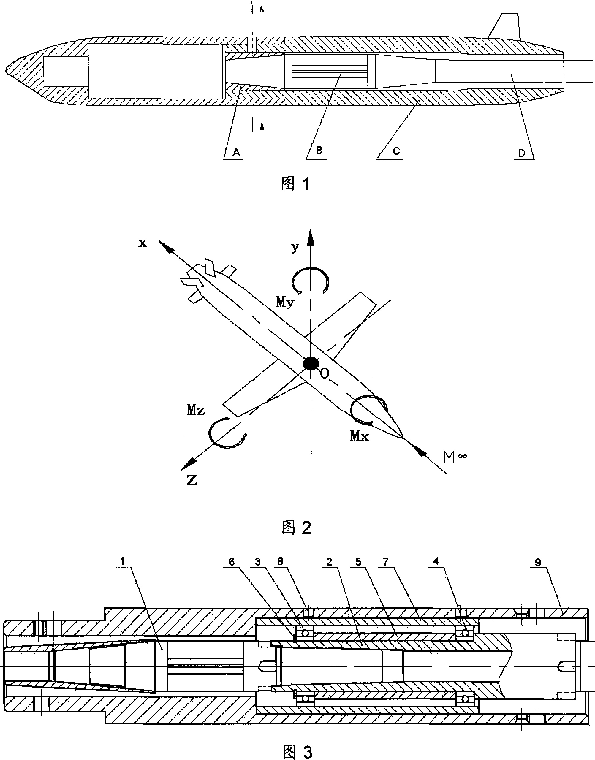
As shown in Figure 1, the front cone of the balance B in the existing balance system is closely matched with the model C through the balance taper sleeve A, and the rear cone of the balance B is matched with the scimitar frame of the wind tunnel through the balance rod D. Since the model C The reason for the resonance with the balance pole D is that the model vibrates within a certain range of Mach number and attack angle, which causes the aerodynamic signal measured by the balance, especially the distortion of the rolling moment signal. The force of the six-component balance is shown in Figure 2 , the X-axis is in the same direction as the incoming air, and the five components in the six-component balance (axial force X, normal force Y, lateral force Z, yaw moment My, pitch moment Mz) interfere with the rolling moment Mx component Larger, increasing the measurement error of the rolling moment
Although a three-component balance without lateral quantities can be designed to improve the reliability and accuracy of rolling moment measurement, the normal force and pitching moment still have a great influence on the rolling moment. Accuracy gains are very limited

Method used


Image

  • Balance system with inhibition structure

Examples


Embodiment Construction

[0011] Below in conjunction with accompanying drawing and specific embodiment the present invention is described in further detail:

[0012] As shown in Figure 3, the present invention includes a six-component internal strain balance 1, a small inner ring shaft 2, a first deep groove ball bearing 3, a second deep groove ball bearing 4, a sleeve 5, a collar 6 and a bearing outer casing 7 , the front end of the small shaft 2 of the inner ring is connected with the rear cone of the six-component internal strain balance 1 through a 1:5 cone fit, and the rear end of the small shaft 2 of the inner ring is connected with the scimitar frame of the wind tunnel through the balance rod; A deep groove ball bearing 3, a second deep groove ball bearing 4 are mechanically matched with the inner ring small shaft 2, and a sleeve is installed between the first deep groove ball bearing 3 and the second deep groove ball bearing 4 on the inner ring small shaft 2 , its purpose is to fix the front a...


PUM


Abstract

The invention provides a balance system with an inhibition structure and comprises a balance, a small inner-ring shaft, a first bearing, a second bearing, a sleeve, a closing ring and a bearing housing. The front end of the small inner-ring shaft is connected with and matches with the back cone of the balance through a cone; the first bearing and the second bearing closely match with the small inner-ring shaft; the sleeve is arranged on the small inner-ring shaft between the first bearing and the second bearing; the first bearing is fixed by the closing ring and the second bearing is fixed by the small inner-ring shaft; the bearing housing closely matches with the first bearing and the second bearing. The inhibition structure of the invention results in that the normal force, the pitching moment, the lateral force and the yawing moment endured by the model in the test can be absorbed by the bearing and the bearing housing in the inhibition structure, therefore, the measurement of the balance cannot be affected and the rolling moment can be transmitted to the balance basically without any loss; thereby, the invention can effectively reduce the interfere of the rolling moment component due to other components of the balance and improve the measuring precision of the rolling moment.

Description

technical field [0001] The invention relates to a balance system for measuring aerodynamic force, in particular to a balance system with a restraining structure, which is mainly used for measuring the rolling moment in a wind tunnel. Background technique [0002] During wind tunnel testing, the most common method is to use a balance system to measure the aerodynamic load on the model. As shown in Figure 1, the front cone of the balance B in the existing balance system is closely matched with the model C through the balance taper sleeve A, and the rear cone of the balance B is matched with the scimitar frame of the wind tunnel through the balance rod D. Since the model C The reason for the resonance with the balance pole D is that the model vibrates within a certain range of Mach number and attack angle, which causes the aerodynamic signal measured by the balance, especially the distortion of the rolling moment signal. The force of the six-component balance is shown in Figure...

Claims


Application Information

Patent Timeline
IPC IPC(8): G01M9/02G01M9/06
Inventor 刘明霞杨辉
Owner CHINA ACAD OF AEROSPACE AERODYNAMICS
Learn More