Time reversal transmitting focusing inverse beamforming method based on high-frequency time reversal array

A time-reversal and beam technology, applied in the field of acoustic detection, can solve problems such as large reverberation, serious delay expansion, and weak detection performance

Inactive Publication Date: 2008-05-21
ZHEJIANG UNIV
View PDF0 Cites 16 Cited by
  • Summary
  • Abstract
  • Description
  • Claims
  • Application Information

AI Technical Summary

Problems solved by technology

For the active detection working mode, the disadvantages are: 1. Multi-channel leads to serio...

Method used


Image

  • Time reversal transmitting focusing inverse beamforming method based on high-frequency time reversal array
  • Time reversal transmitting focusing inverse beamforming method based on high-frequency time reversal array
  • Time reversal transmitting focusing inverse beamforming method based on high-frequency time reversal array

Examples


Embodiment Construction

[0054] The present invention will be further described below in conjunction with the accompanying drawings.

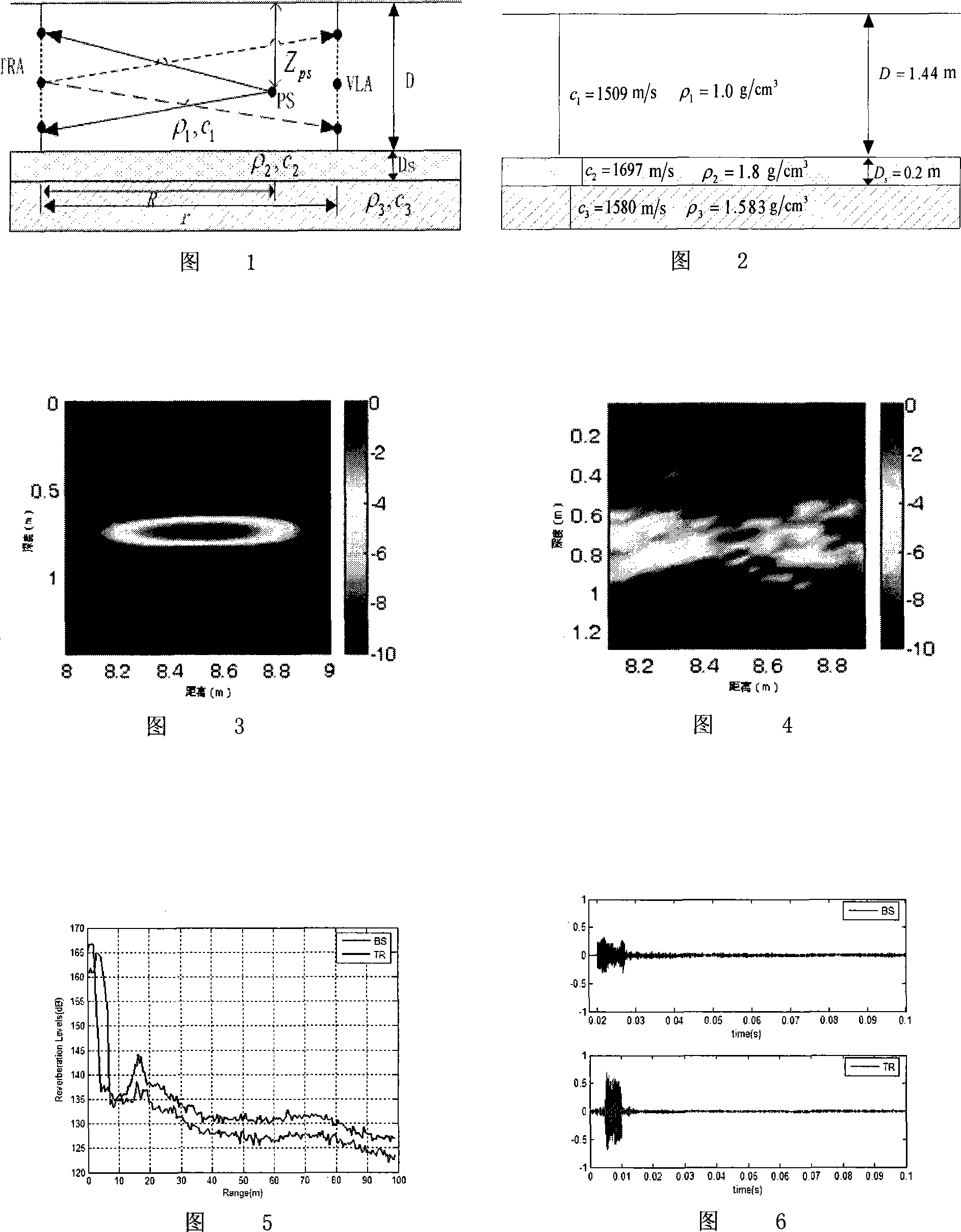
[0055] Referring to Figure 2, design and actual measurement results of mirror performance parameters at high frequencies: Table 1 lists the physical parameters of the mirror at high frequencies. Figure 2 is the acoustic parameter model of the laboratory waveguide experiment environment, using a time-anti-array, a probe source, and a vertical line array that is anti-focused when monitoring the sound field. The layout of each device in the time-deflecting focusing experiment is shown in Figure 1. TRA and VLA are deployed from 4cm underwater to 128cm underwater, and the distance between the two arrays is 9.6m. The distance between PS and TRA is 9.6m, and it is located at 74cm underwater. The PS source emits a narrowband raised cosine envelope PCW signal with a center frequency of 20kHz and a bandwidth of 2.4kHz. Fig. 3 and Fig. 4 respectively show the space (depth-dist...


PUM


Abstract

The present invention provides a time-reversal emission focusing reverse beam forming method based on high frequency time-reversal array. The beam forming method uses high frequency time-reversal array. A sound wave is emitted to irradiate the object and an echo signal from the object is received. The received echo signal is turned on time and emitted back. The time-reversal signal can focus at the object place, which performs as time waveform compression and space-focusing. An enhanced object echo signal is received again to form a receiving focusing beam. The present invention provides the time-reversal emission focusing reverse beam forming method based on the high frequency time-reversal array which uses a high frequency time-reversal mirror which is suitable for shallow water acoustic fields, reduces the reverberation and improves the detection ability to shallow water.

Description

technical field [0001] The invention relates to an acoustic detection technology in the development and utilization of marine resources, in particular to a beam forming method for reducing reverberation and improving signal-to-mix ratio in shallow sea. Background technique [0002] The shallow sea sound field is a waveguide with the sea surface above and the sea bottom below. The sound wave has a direct path and a reflection path from the upper and lower interfaces. However, the existing underwater acoustic equipment assumes that the ocean is a free field and has no boundaries, and uses a plane wave model for processing. Therefore, They all suffer from reduced performance when operating in shallow or near-shore waters. For the active detection working mode, the disadvantages are: 1. Multiple channels cause serious delay expansion; 2. Large reverberation and low back-mixing ratio; 3. Weak detection performance. Contents of the invention [0003] In order to suppress the re...

Claims


Application Information

Patent Timeline
IPC IPC(8): G01S15/02G01S15/08G01S7/539G01V1/00
Inventor 潘翔赵航芳李建龙宫先仪
Owner ZHEJIANG UNIV
Why Eureka
Try Eureka