Decelerator for control motor

A reducer and step technology, applied in the field of precision reducers, can solve the problems of fast wear, long working time, reduced gear efficiency, etc., and achieve the effects of high transmission efficiency, long service life and easy installation.

Inactive Publication Date: 2008-05-21
重庆创坤科技发展股份有限公司
View PDF0 Cites 13 Cited by
  • Summary
  • Abstract
  • Description
  • Claims
  • Application Information

AI Technical Summary

Problems solved by technology

[0002] In the prior art, the most common control motor reducers are mainly PX and PL series planetary reducers. The center gears of these reducers are complicated to process, with a large number of gears and high cost. The working time is long, and the three planetary gears are involved in the meshing work at the same time, the wear is fast, and the processing requirements of the planetary carrier are high
Moreover, the reduction ratio of the reducer in the serialized products cannot be increased in numerical order, but can only be increased in multiples of the base number, such as 5, 8, 12, 15, 20, etc., to increase the reduction ratio, the number of gears needs to be increased, and at the same time As the number of stages increases, the efficiency of the gear will also decrease
Since the gears of this series of reducers are planetary arranged according to the radial structure, in the case of a certain radial size, the gear and the gear shaft are limited by the radial size, and bearings cannot be installed, which will cause sliding friction and increase energy consumption. increase, and it is not easy to increase the modulus in structure to improve the gear strength. In the reduction ratio of the same level, the torsional strength of the reducer does not match the reduction ratio of the reducer

Method used


Image

  • Decelerator for control motor
  • Decelerator for control motor
  • Decelerator for control motor

Examples


Embodiment 1

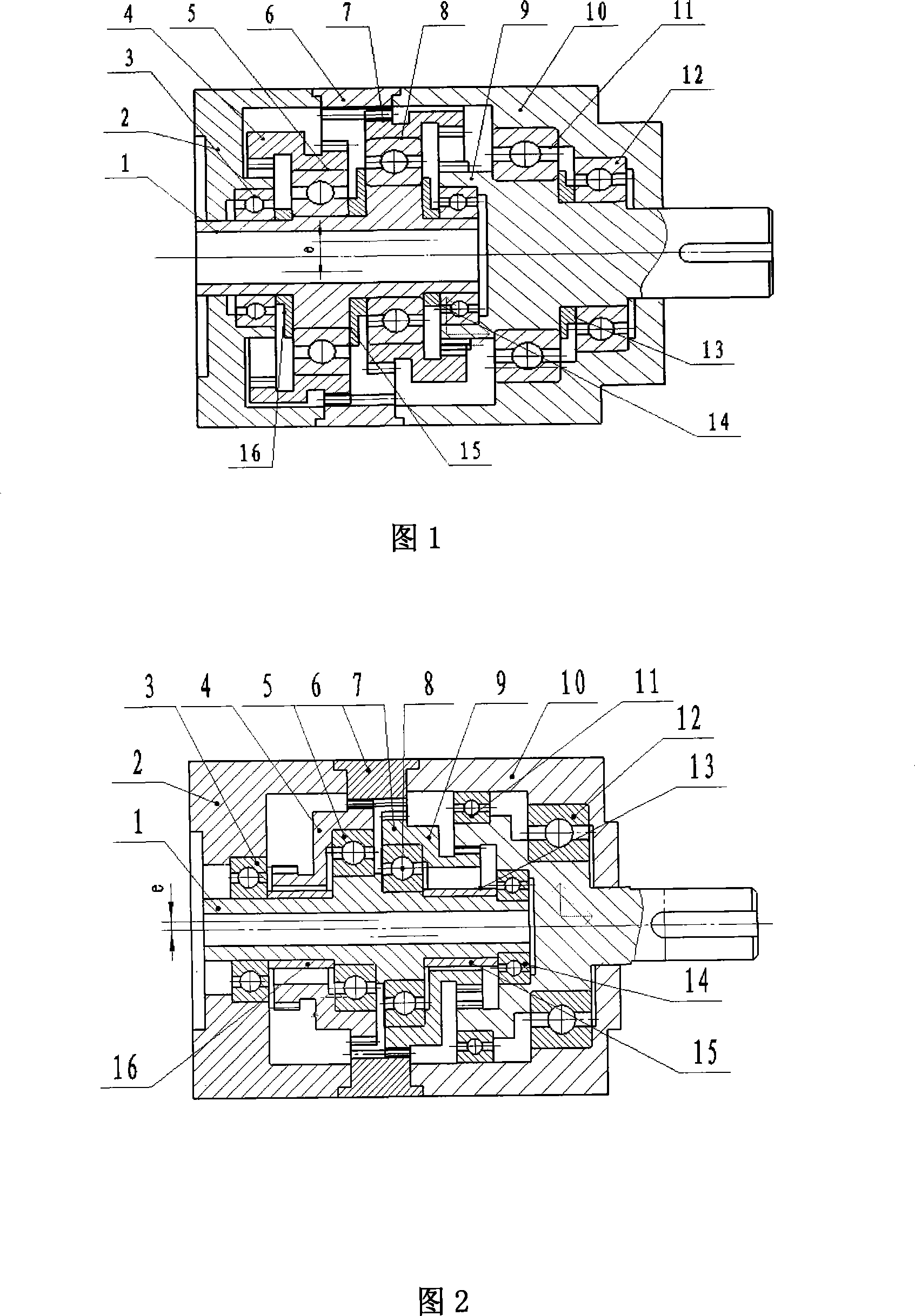
[0014] Embodiment 1: as shown in Figure 1, a kind of speed reducer for controlling motor is made up of input shaft 1, stepped planetary gear 4,7 (stepped planetary gear 4,7 are all made up of an external gear and internal gear), internal gear 6 , output shaft 9, right housing 10, left housing 2, support bearings 3, 14 of input shaft 1, support bearings 5, 8 of two stepped planetary gears 4, 7, and support bearings 11, 12 of output shaft 9 constitute. Among the figure, 13,15,16 all are retaining rings.

[0015] The input shaft 1 is supported by the first support bearing 3 and the second support bearing 14 respectively in the inner hole of the left housing 2 and the left end of the output shaft 9. There are two pairs of eccentric circles with a circumferential difference of 180° in the middle of the input shaft 1. The third support bearing 5 and the fourth support bearing 8 are installed on the circle, the inner hole of the stepped planetary gear 4 is sleeved on the outer ring ...

Embodiment 2

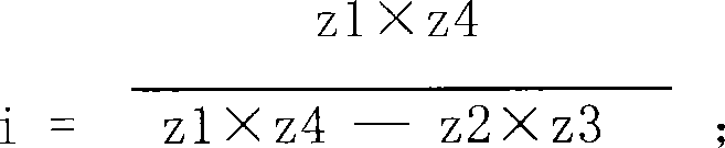
[0020] Embodiment 2: The difference from the first structure is that the teeth on the two-step planetary gears 4 and 7 are all external teeth, and the left end of the output shaft 9 has a ring of internal teeth, and the rest of the structure is the same as the first structure.

[0021] As shown in Figure 2: the reducer mainly includes an input shaft 1, a first stepped planetary gear 4, a second stepped planetary gear 7, an internal gear 6 and an output shaft 9, as well as a first support bearing 3 for supporting the input shaft 1 and The second support bearing 14 is used to support the third support bearing 5 and the fourth support bearing 8 of the two-step planetary gears 4 and 7 , and the fifth support bearing 11 and the sixth support bearing 12 are used to support the output shaft 9 . Among the figure, 2 is the right housing, 10 is the left housing, and 13 is a retaining ring.

[0022] The input shaft 1 is supported by the first support bearing 3 and the second bearing 14 r...

Embodiment 3

[0028] Embodiment 3: Figures are omitted, the two-stage planetary gears are both external gears, and the modulus difference between the first-stage and second-stage gears in the meshing of two-stage internal and external gears is 0.25, such as 1.25 for the first stage and 1.5 for the second stage , by adjusting the displacement coefficient x to ensure that the center distance between the two pairs of gears is e.

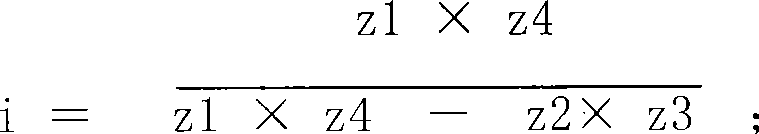
[0029] transmission ratio i = z 1 × z 4 z 1 × z 4 - z 2 × z 3 ; zi and z3 are the external teeth of the stepped planetary gear, z2 is the internal tooth of the internal gear 6; z4 is the internal tooth fixed on the output shaft.

[0030] z1=z3,...


PUM


Abstract

The invention relates to a speed reducer used for controlling a motor, which comprises an input shaft, a step planetary gear, an internal gear, an output shaft, a right housing, a left housing and a plurality of support bearings. The invention has the advantages that: a high rotational speed meshing is arranged for the gear of the speed reducer, so the processing of the gear is simple with low noise and little heat generating, which is especially obvious with the reducing speed ratio increasing; rolling bearing matching is adopted for the gear and the bearing with high efficiency and convenient installation of the output and the input shafts; 4 to 7 gears participate in meshing work when the gear is meshed with good equal load property, little heat generating, low noise and long service life due to low speed meshing of the gear; four gears can form a speed reducer with less than 100 of drive ratio, thereby adapting to requirement of each sequence reduction ratio and facilitating serial production; reasonable addendum coefficient, modification coefficient and serrated angle of pressure are adopted, thereby achieving a higher transmission efficiency.

Description

technical field [0001] The invention relates to a precision reducer suitable for controlling a motor, which belongs to the technical field of mechanical transmission. Background technique [0002] In the prior art, the most common control motor reducers are mainly PX and PL series planetary reducers. The center gears of these reducers are complicated to process, with a large number of gears and high cost. The working time is long, and it is involved in the meshing work with three planetary wheels at the same time, the wear is fast, and the processing requirements of the planetary carrier are high. Moreover, the reduction ratio of the reducer in the serialized products cannot be increased in numerical order, but can only be increased in multiples of the base number, such as 5, 8, 12, 15, 20, etc., to increase the reduction ratio, the number of gears needs to be increased, and at the same time Increasing the number of stages will also reduce the efficiency of the gear. Since...

Claims


Application Information

Patent Timeline
Patent Type & Authority Applications(China)
IPC IPC(8): H02K7/116
Inventor 胡捷
Owner 重庆创坤科技发展股份有限公司
Why Eureka
Try Eureka