Master cylinder

A technology for cylinder bores and housings, applied in hydraulic brake transmissions, brakes, transportation and packaging, etc., which can solve the problems of poor piston assembly, reduced piston guidance, and a large number of parts, and shorten the invalid stroke , Reduce the processing procedure, the effect of easy processing

Inactive Publication Date: 2008-05-21
BOSCH CORP
View PDF2 Cites 14 Cited by
  • Summary
  • Abstract
  • Description
  • Claims
  • Application Information

AI Technical Summary

Problems solved by technology

However, if the diameter of the front portion of the piston is reduced in this way, the front portion of the piston cannot be guided by the axial hole of the cylinder, and the guiding performance of the piston is reduced.
[0015] In addition, in the master cylinder disclosed in JP-A-2000-142364, the replenishment of the brake fluid is ensured by providing a sufficient brake fluid passage area, but the sleeve must be fitted to the front end of the piston. And the fitted sleeve must be prevented from falling off in the axial direction by means of a retainer
Therefore, not only the number of parts is large, but also the assembly of the piston is not good.

Method used


Image

  • Master cylinder
  • Master cylinder
  • Master cylinder

Examples


Embodiment Construction

[0027] The best mode for implementing the present invention will be described below with reference to the accompanying drawings. In the following descriptions, "front" and "rear", the direction in which the piston moves when the master cylinder is working is "front", and the direction in which the piston retreats when the master cylinder is stopped is "rear", both are used in the respective descriptions "Left" and "Right" in the attached drawings.

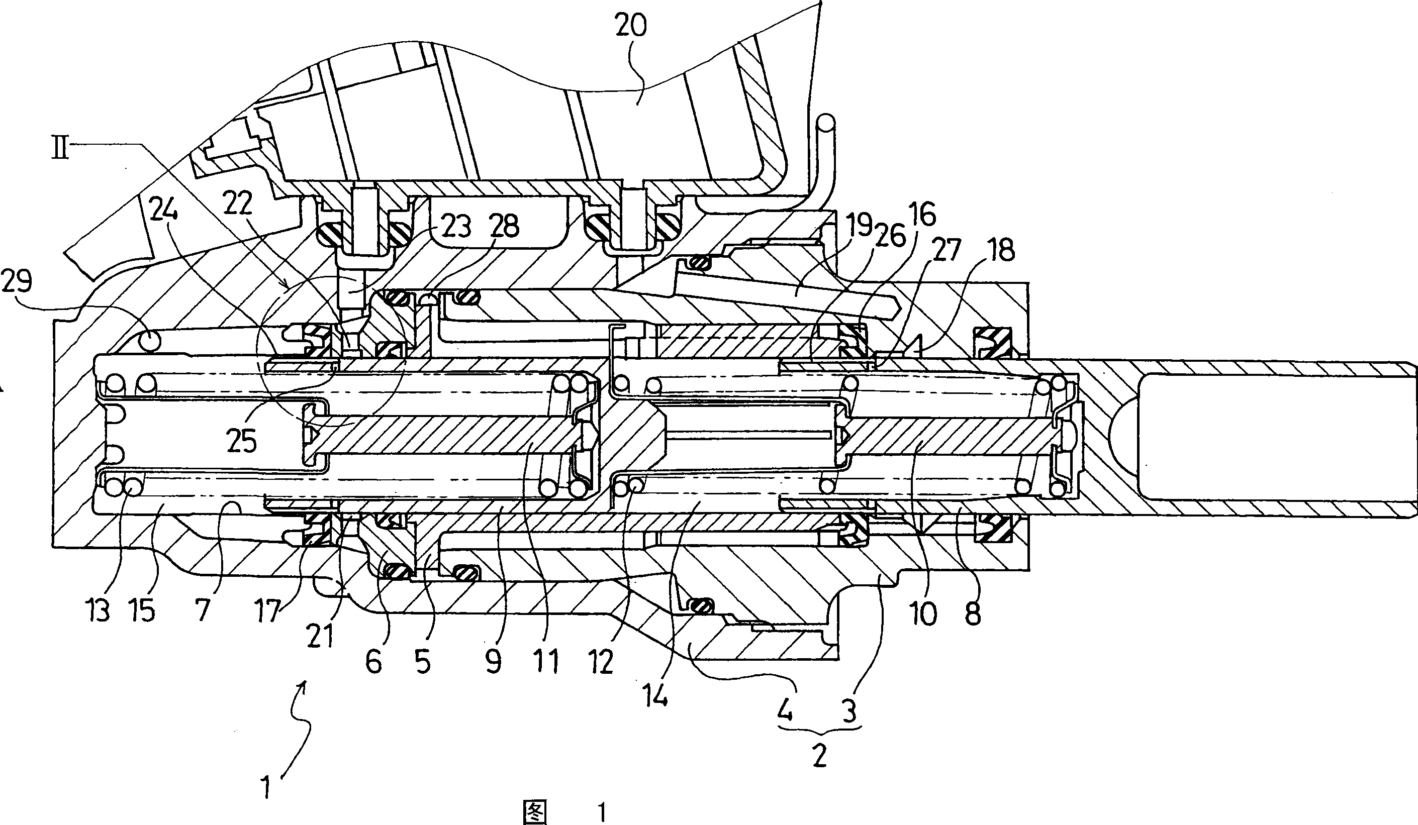
[0028] FIG. 1 is a longitudinal sectional view showing an example of an embodiment of the master cylinder of the present invention.

[0029] As shown in FIG. 1 , the master cylinder 1 of this example has a cylinder housing 2 composed of a first cylinder member 3 and a second cylinder member 4 fitted and fixed to the first cylinder member 3 . A first piston guide 5 and a second piston guide 6 are held axially between the first cylinder part 3 and the second cylinder part 4 .

[0030] A cylinder bore 7 extending in the axial direct...


PUM


Abstract

A master cylinder is provided with a secondary piston (9) having a predetermined number of second axial grooves (24) formed, at predetermined intervals in the circumferential direction, in the outer circumferential surface of a head section of the piston (9). Second radial holes (25) are formed in rear end sections of some of the second axial grooves (24), penetrating between the inner and outer circumferential surfaces of the piston (9). When the cylinder is not operated, a rear end section of the second axial grooves (24) and the second radial holes (25) are together closer to the rear side than a seal point A of a second cup seal (17), and as a result, a second liquid chamber (21) and a second liquid pressure chamber (15) are communicated via the second axial grooves (24) and the second radial holes (25). Further, when the rear end sections of the second axial holes (24) and the second radial holes (25) are closer to the front side than the seal point A, the second liquid chamber (21) and the second liquid pressure chamber (15) are cut out. By this, the piston is more easily worked and the strength of the piston is ensured, with ease of brake fluid supply assured.

Description

technical field [0001] The technical field of the present invention relates to a master cylinder, which is used in a braking system of a vehicle such as an automobile, and generates master cylinder pressure for operating the brakes, and in particular relates to the technical field of a master cylinder that will The performance of replenishing the brake fluid from the reservoir to the hydraulic chamber, that is, the replenishment, and the braking operation by the driver, such as automatic braking, take into account the fact that the brake fluid passes through an external power source such as a pump when the brake is operating. The drive is sucked into the performance of the hydraulic chamber side of the master cylinder, that is, the self-contained master cylinder. Background technique [0002] For example, conventionally, a brake system of an automobile has a master cylinder that generates master cylinder pressure when the brake pedal is depressed, and supplies the master cyl...

Claims


Application Information

Patent Timeline
Patent Type & Authority Applications(China)
IPC IPC(8): B60T11/16
CPCB60T11/16B60T11/228B60T11/232B60T11/236
Inventor 平和久
Owner BOSCH CORP
Why Eureka
Try Eureka