Check patentability & draft patents in minutes with Patsnap Eureka AI!

Diversity combining method and diversity receiver apparatus

A receiving device and diversity technology, applied in space transmit diversity, diversity/multi-antenna system, channel estimation, etc.

Inactive Publication Date: 2011-09-21
PANASONIC CORP
View PDF2 Cites 0 Cited by
  • Summary
  • Abstract
  • Description
  • Claims
  • Application Information

AI Technical Summary

Problems solved by technology

[0020] However, in the technique described in Patent Document 2, when the received signal point deviates greatly from the transmitted code point, a hard decision is made on a code point different from the original transmission code point, etc., and each demodulation unit There is a limit to the improvement of the receiving characteristics of the receiver, and the improvement of the performance of diversity reception

Method used


Image

  • Diversity combining method and diversity receiver apparatus
  • Diversity combining method and diversity receiver apparatus
  • Diversity combining method and diversity receiver apparatus

Examples


Embodiment approach 1

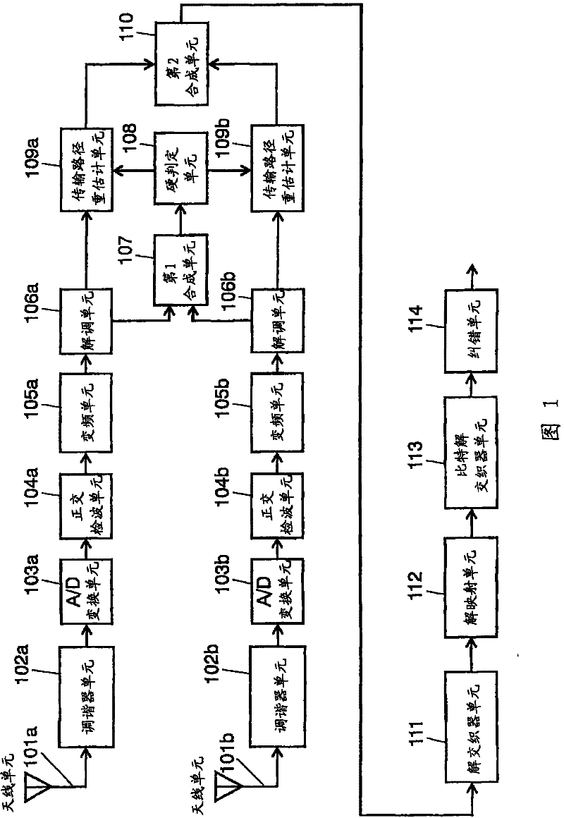
[0068] use figure 1 ˜FIG. 5 describe a configuration example of an apparatus for realizing the diversity reception method in Embodiment 1 of the present invention. figure 1 It is a block diagram showing the configuration of the diversity receiving apparatus in Embodiment 1 of the present invention. exist figure 1 Among them, the diversity receiving apparatus in Embodiment 1 includes: antenna units 101a, 101b, tuner units 102a, 102b, A / D conversion units 103a, 103b, quadrature detection units 104a, 104b, frequency conversion units 105a, 105b, Demodulation unit 106a, 106b, first synthesis unit 107, hard decision unit 108, transmission path reestimation unit 109a, 109b, second synthesis unit 110, deinterleaver unit 111, demapping unit 112, bit deinterleaver unit 113 , and 114 as an error correction unit. Here, the antenna unit 101a and the antenna unit 101b are different from each other in at least one of their installation positions and characteristics.

[0069] In Embodimen...

Embodiment approach 2

[0105] use Figure 6 , Figure 7 , Figure 8A , Figure 8B A configuration example of an apparatus for realizing the diversity reception method according to Embodiment 2 of the present invention will be described. In Embodiment 2, a diversity reception apparatus having two systems from the antenna unit to the demodulation unit will be described as an example.

[0106] Figure 6 It is a block diagram showing the configuration of the diversity receiving apparatus in Embodiment 2 of the present invention. In the second embodiment, the first combination unit 107 in the first embodiment is replaced with the first combination unit 115, and the transmission path reestimation units 109a and 109b in the first embodiment are replaced with the transmission path re-estimation unit 115. Estimation units 116a and 116b. Therefore, components other than the first combination unit 115 and the channel reestimation units 116a and 116b are the same as those in the first embodiment, and ther...

Embodiment approach 3

[0126] use Figure 9 , Figure 10 A configuration example of an apparatus for realizing the diversity reception method according to Embodiment 3 of the present invention will be described. In Embodiment 3, a diversity reception apparatus having two systems from the antenna unit to the demodulation unit will be described as an example.

[0127] Figure 9 It is a block diagram showing a configuration example of a diversity receiving apparatus in Embodiment 3 of the present invention. In Embodiment 3, the synthesis unit 117 replaces the first synthesis unit 107 and the second synthesis unit 110 in the first embodiment. Therefore, since the components other than the synthesis unit 117 have the same structure as that of the first embodiment, description thereof will be omitted.

[0128] Figure 9 The synthesis unit 117 in the figure 1 Compared with the first combination unit 107 of the above, the difference is that the signals from the channel re-estimation units 109 a and 10...


PUM


Abstract

In a diversity receiver apparatus, which demodulates each of a plurality of signals received via a plurality of antennas and uses the demodulated signals, the number of which is the same as the number of the antennas, to perform a signal demodulation, a first combining part (107) once combines the plurality of signals, and a hard decision part (108) performs a hard decision of the combining result to figure out a likely coding point. Transmission path re-estimating parts (109a, 109b) use this likely coding point to figure out a transmission path characteristic with a high estimation accuracy. The transmission path characteristic is used to perform a dividing calculation of the demodulated signals the number of which is the same as the number of the antennas. The resultant signals are re-combined by a second combining part (110), whereby a demodulation result of high reliability can be obtained.

Description

technical field [0001] The present invention relates to the technique of performing diversity reception on the data signal sequence modulated by the digital multi-ary system modulation mode. Background technique [0002] In video receivers installed in automobiles, mobile phones, etc., in order to receive terrestrial broadcast waves stably even while moving, a diversity reception method is often used. [0003] As the diversity reception scheme, the following schemes have been proposed: a space diversity scheme, a time diversity scheme, a frequency diversity scheme, a polarization diversity scheme, and the like. In general, for the purpose of improving reception characteristics of terrestrial broadcast waves, in order to effectively use limited frequency resources, a space diversity method that can be realized by changing the receiving method at the receiving end is often used. [0004] For example, in the case of receiving analog TV broadcasts in a moving car, a space diver...

Claims


Application Information

Patent Timeline
Patent Type & Authority Patents(China)
IPC IPC(8): H04B7/08H04J11/00H04L27/38
CPCH04B7/0845H04L25/0232H04B7/0848H04B7/0885H04L27/2647H04L25/0204
Inventor 谷口友彦木曾田晃
Owner PANASONIC CORP
Features
  • R&D
  • Intellectual Property
  • Life Sciences
  • Materials
  • Tech Scout
  • Unparalleled Data Quality
  • Higher Quality Content
  • 60% Fewer Hallucinations
Learn More