Bottom end stop for slide fastener

A code-stop and zipper technology, applied in the back-stop field to achieve excellent appearance

Active Publication Date: 2008-05-28
YKK CORP
View PDF2 Cites 13 Cited by
  • Summary
  • Abstract
  • Description
  • Claims
  • Application Information

AI Technical Summary

Problems solved by technology

Therefore, it is difficult to form decorations such as characters, marks or patterns on the surface of the end stop 306.

Method used


Image

  • Bottom end stop for slide fastener
  • Bottom end stop for slide fastener
  • Bottom end stop for slide fastener

Examples


no. 1 approach

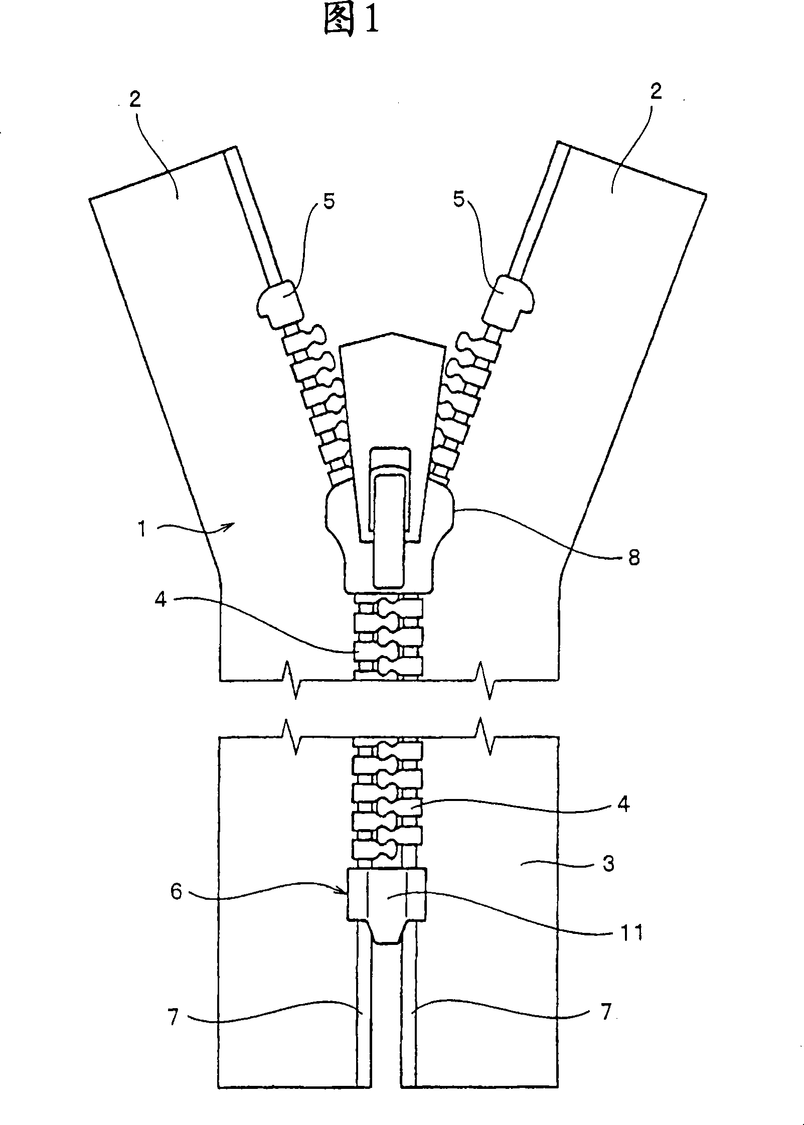
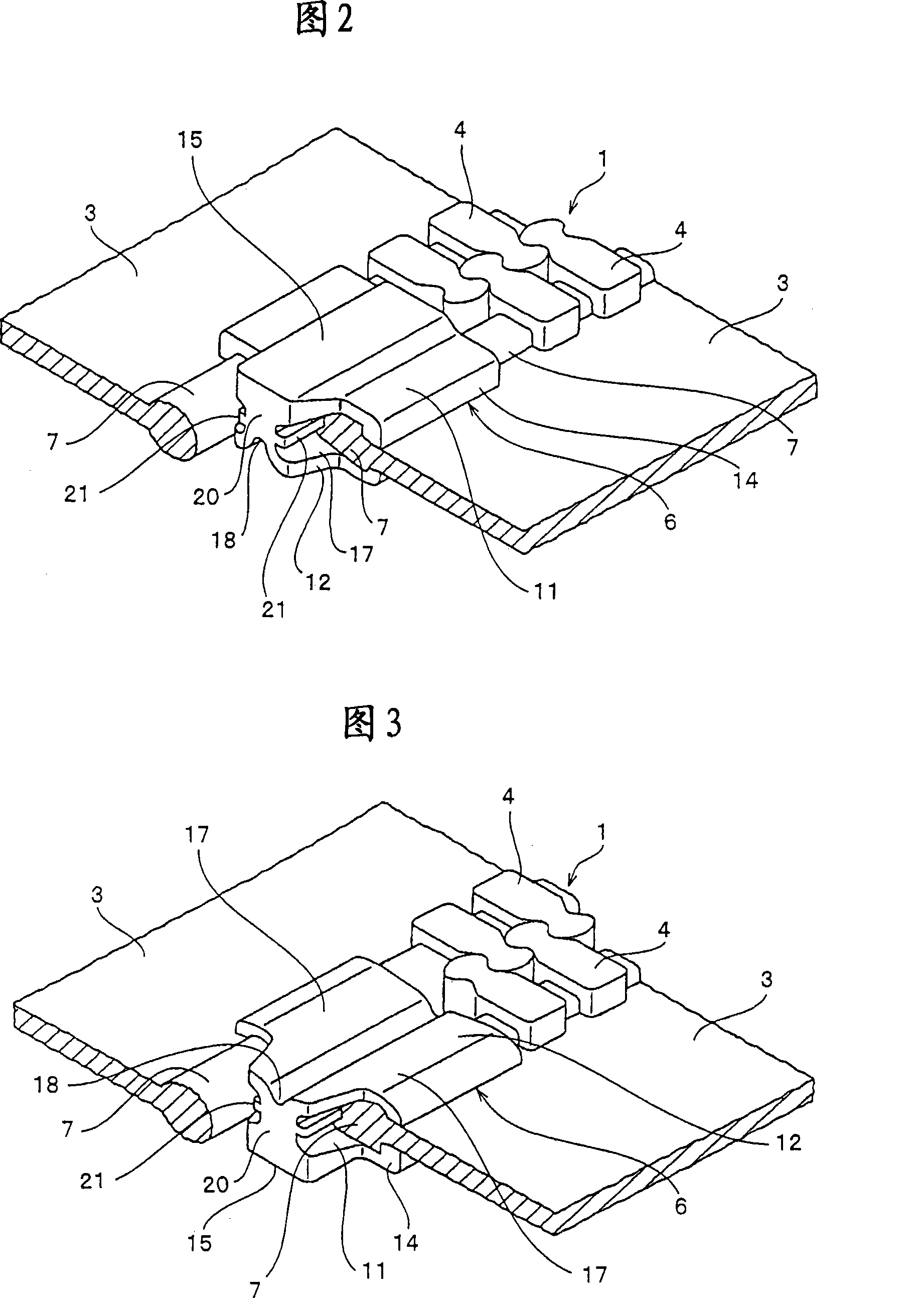
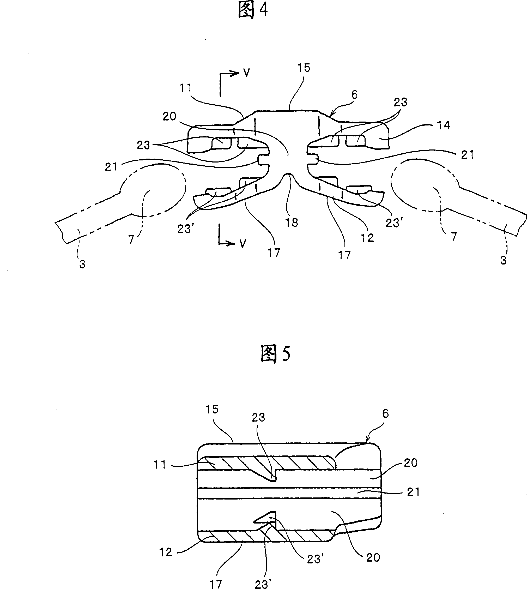
[0043] The bottom end stop 6 used in the slide fastener according to the first embodiment shown in FIGS. 1 to 6 is molded from a metal such as aluminum alloy or zinc alloy by a die-casting device. The bottom end stop 6 is formed by an upper plate 11 , a lower plate 12 and a base 20 . The upper plate 11 is formed such that its thickness increases continuously along the length direction of the slide fastener, thereby forming a raised portion 15 on the surface of the upper plate 11 . The surface of the raised portion 15 is flat, and when the bottom stop 6 is formed, decorations such as letters, marks, and patterns are expressed by engraving or in post-processing.

[0044] Both sides of a raised portion 15 formed in the middle of the upper plate 11 extend flatly to the left and right, and flanges 14 are formed on both sides of the raised portion so that the flanges 14 are bent downward at right angles to the upper plate 11 . Decorations such as letters, marks, and patterns may be...

no. 2 approach

[0052] The bottom end stop 6 for a slide fastener according to the second embodiment shown in FIG. 7 is formed of an upper plate 11 , a lower plate 12 and a base 20 , and the surface of the upper plate 11 is flat. The flange 14 is formed by bending both side ends at right angles, and the surface of the upper plate 11 is formed in such a configuration that decorations such as letters, marks, and patterns can be expressed. A groove portion 18 having a circular cross section is concavely formed in the middle of the rear surface of the lower plate 12 in the left-right direction, and arm portions 17 are formed on the right and left sides of the groove portion 18 so that the arm portion 17 is formed from the groove portion. 18 in a row. The base 20 is provided to connect the upper plate 11 and the lower plate 12 in a vertical direction, and a protrusion 21 is formed on a side surface of the base 20 to reinforce the base 20 .

[0053] The bottom end stop 6 has a square shape in plan...


PUM


Abstract

The invention relates to a bottom stop for a zipper. The bottom stop is composed of an upper plate, a lower plate and a base. The upper plate is formed of a non-deformable flat plate, and has flanges formed on each side end of the upper plate by bending each side end of the upper plate at a right angle. A groove with a circular cross-section is provided in the middle of the back of the lower plate, and arms are provided on both sides of the groove so that the arms are gradually separated from the upper plate, and the middle parts of the upper and lower plates are connected by the base. Decorations such as characters, marks or patterns are represented on the surface of the upper plate. The core of the zipper tape is sandwiched between the upper and lower panels on the right and left sides of the base, and the arms of the lower panel are plastically deformed to the upper panel to attach the bottom stop preventing cracks in the bottom stop , thereby enabling decorations such as letters, marks, and patterns to be simply expressed on the surface of the bottom stop, and preventing cracks from being generated in the lower plate when the bottom stop is attached.

Description

technical field [0001] The present invention relates to a stopper attached to a core, wherein the core is formed on a fastener tape adjacent to elements in a slide fastener employing fastener tapes, each of the fastener tapes being on one of its Having a core on the sides, said stop has the function of stopping the sliding of the slider, and more particularly relates to a back stop for zippers made of metal. Background technique [0002] According to US Patent Publication No. 2,884,691, a conventional bottom stop for a zipper is constructed as shown in Figures 8 and 9, wherein the bottom stop can be easily attached to the sides of the zipper tape. Specifically, the main body 210 of the bottom end stop has an acute-angled groove portion 218, curved branch wall portions 217 formed on the right and left sides of the rear surface, and a flat bottom surface formed in the middle of the rear surface. 218 is formed in the middle of the curved branch wall portions 217 formed on the ...

Claims


Application Information

Patent Timeline
Patent Type & Authority Applications(China)
IPC IPC(8): A44B19/36
CPCA44B19/36Y10T24/2593
Inventor 大角美幸
Owner YKK CORP
Why Eureka
Try Eureka