Laser grinding wheel trimming device with double tangential liquid column flows and trimming method thereof

A laser dressing and grinding wheel technology, used in abrasive surface adjustment devices, parts of grinding machine tools, grinding/polishing equipment, etc., can solve problems such as micro-cracks, and achieve the purpose of inhibiting movement, reducing the influence of residual heat, and inhibiting the effect of energy accumulation. Effect

Active Publication Date: 2014-05-21
HUNAN UNIV
View PDF6 Cites 4 Cited by
  • Summary
  • Abstract
  • Description
  • Claims
  • Application Information

AI Technical Summary

Problems solved by technology

[0005] In order to overcome the deficiencies and defects of the prior art, a grinding wheel laser dressing device with double tangential liquid column flow and its method are invented. In the grinding wheel dressing, the water-liquid cooling effect is used for the first time, and the emulsified liquid is added to form a laser dressing on the surface of the grinding wheel. A layer of liquid film can improve the surface evaporation of the liquid, expand contact heat dissipation, and promote radiation heat exchange. Under the action of double tangential liquid column flow, the occurrence of phase explosion on the surface of the grinding wheel under the action of high-power laser ablation is suppressed, and the splash is reduced. Re-solidification avoids clogging pits, inhibits the movement of the solid-liquid phase interface in the superheated layer after the end of the pulse laser, suppresses the energy accumulation effect, and avoids the secondary heat conduction of the bonding agent and abrasive under high-power laser ablation. Defects such as microcracks and graphite metamorphic layers, thereby improving the surface quality after reconditioning

Method used


Image

  • Laser grinding wheel trimming device with double tangential liquid column flows and trimming method thereof
  • Laser grinding wheel trimming device with double tangential liquid column flows and trimming method thereof
  • Laser grinding wheel trimming device with double tangential liquid column flows and trimming method thereof

Examples


Embodiment Construction

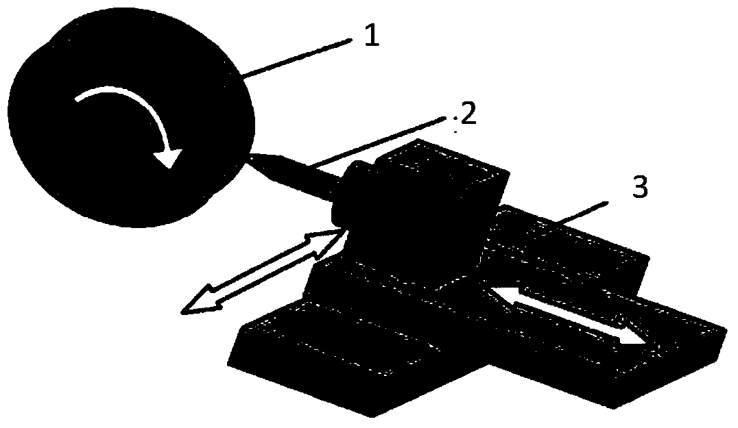
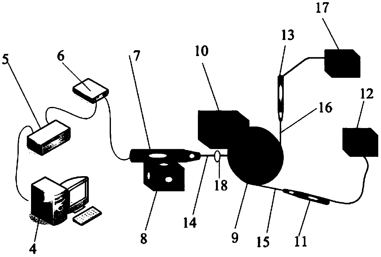
[0023] The following will be attached image 3 The specific technical solution of the present invention is described in detail.

[0024] Such as image 3 As shown, the laser dressing device for grinding wheels with dual tangential liquid column flows according to the present invention includes computer control equipment 4, control operation platform 5, fiber laser 6, laser ablation head 7, three-dimensional mobile platform 8, super hard Abrasive grinding wheel 9, grinding machine 10, lower tangential water pipe 11, lower tangential liquid column pressure controller 12, right tangential water pipe 13, laser beam 14, lower tangential liquid column flow 15, right tangential liquid column flow 16, right cut To the liquid column pressure controller 17, focus lens 18 and so on.

[0025] The super-abrasive grinding wheel 9 is installed on the controllable grinder 10. The grinder 10 drives the grinding wheel to rotate. The laser ablation head 7 is fixed on the three-dimensional moving plat...


PUM


Abstract

The invention relates to a laser grinding wheel trimming device with double tangential liquid column flows. The laser grinding wheel trimming device comprises computer control equipment (4), a control operating platform (5), a fiber laser device (6), a laser ablation head (7), a three-dimensional moving platform (8), an ultrahard abrasive grinding wheel (9), a grinder (10), a lower tangential thin water pipe (11), a lower tangential liquid column pressure controller (12), a right tangential thin water pipe (13), a laser beam (14), the lower tangential liquid column flow (15), the right tangential liquid column flow (16), a right tangential liquid column pressure controller (17) and a focusing lens (18). The auxiliary double-tangential-liquid-column-flow device is provided, so that the energy accumulation effect is suppressed, and energy balance in the trimming process is improved. In addition, a liquid film is formed on the surface of a grinding wheel, so that heat loss of an evaporation effect is reduced, the use ratio of laser is improved, and surface quality of the trimmed grinding wheel is improved.

Description

Technical field [0001] The invention relates to a super-hard abrasive grinding wheel dressing device and a dressing method, in particular to a grinding wheel laser dressing device with double tangential liquid column flow and a dressing method. Background technique [0002] Super-hard abrasive grinding wheels refer to cubic boron nitride and diamond grinding wheels, which have extremely high hardness and strong wear resistance, but because of their extremely high hardness, dressing is very difficult. Therefore, in order to make the ultra-thin and super-hard material grinding wheel can maintain the geometric shape and the sharpness of the abrasive grains during the cutting process, it needs to be trimmed regularly. Traditional mechanical trimming methods such as figure 1 Shown (such as turning method, extrusion method, rolling method) are based on the "hard-to-hard" effect of force, so there are fatal flaws, that is, the efficiency is very low, the dressing tool wears serious, and...

Claims


Application Information

Patent Timeline
Patent Type & Authority Applications(China)
IPC IPC(8): B24B53/06
CPCB24B53/06B24B53/095
Inventor 陈根余蔡颂周聪陈洪星周兴才何杰邓辉张玲陈俊张勇王大伟杜晗
Owner HUNAN UNIV
Why Eureka
Try Eureka