Wind-driven generator

A technology for wind turbines and motor shafts, which is applied to wind turbines, wind turbine combinations, wind energy power generation, etc., can solve the problems of easy breakage of solid shafts, thick motor shafts, and high cost, and achieve overall stability and balance. The effect of reducing weight and cost, extending the service life

Inactive Publication Date: 2008-05-28
JIANGSU NEWHOPE RENEWABLE ENERGY S & T
View PDF0 Cites 6 Cited by
  • Summary
  • Abstract
  • Description
  • Claims
  • Application Information

AI Technical Summary

Problems solved by technology

[0003] The disadvantage of using a solid-shaft motor for wind turbines is that this wind turbine generates electricity by rotating the solid shaft of the motor through the rotation of the blades.
Since the wind turbine works day and night for 24 hours, the solid shaft is easy to break after a certain period of time. In order to strengthen the strength of the motor shaft and prolong the service life of the motor, the method of increasing the diameter of the motor shaft is used in the prior art to solve the problem.
In order to obtain a high-power wind turbine, the motor shaft will be very thick, and the motor will be very heavy
Moreover, the central support of the entire wind turbine is constantly rotating, which affects the stability of the overall device
The above-mentioned British company’s products also use hard materials to make the blades integrally. The blades are shaped, and special molds are required to shape the blades, which is complex and costly. 3m, the length of the blade is 6m, the overall size of the supporting part is large, the manufacturing cost is high, and it is difficult to transport and install; the finished part is welded to the blade, and the strength is poor under the strong wind for a long time; the longitudinal central axis and the supporting part rotate at the same time, and the balance and stability are not good

Method used


Image

  • Wind-driven generator
  • Wind-driven generator
  • Wind-driven generator

Examples


Embodiment 1

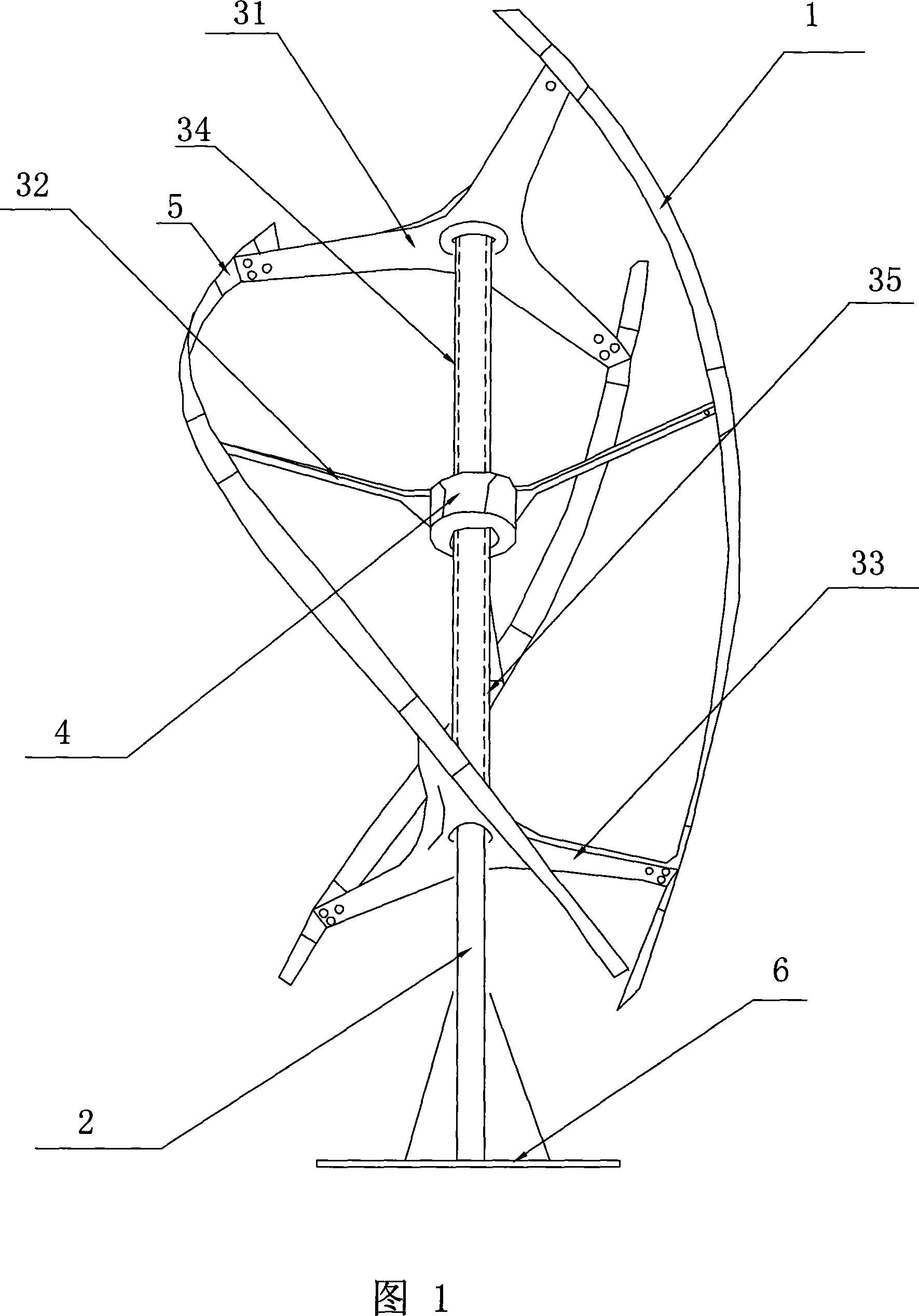
[0065] As shown in Figure 1, the present invention comprises three independent blades 1, a longitudinal central axis 2, an upper support 31, a middle support 32 and a lower part which are horizontally arranged on the upper, middle and lower parts of the longitudinal central axis 2 and which can rotate around the longitudinal central axis 2 Support 33, motor 4 can be fixedly connected with any support.

[0066] As shown in FIG. 1 , the motor 4 is set at the center of the middle bracket 32 ​​. As shown in FIG. 7 , the longitudinal center shaft 2 passes through the hollow shaft 42 and has an interference fit with it. The longitudinal central axis 2 does not rotate, and the motor 4 and each support rotate around the longitudinal central axis 2. Therefore, compared with the prior art, for a motor with the same power, the hollow shaft 42 not only reduces the cost compared to the solid shaft, but also greatly reduces the weight of the motor itself.

[0067] The structure of the mot...

Embodiment 2

[0076] The motor 4 in the first embodiment can also adopt the following structure:

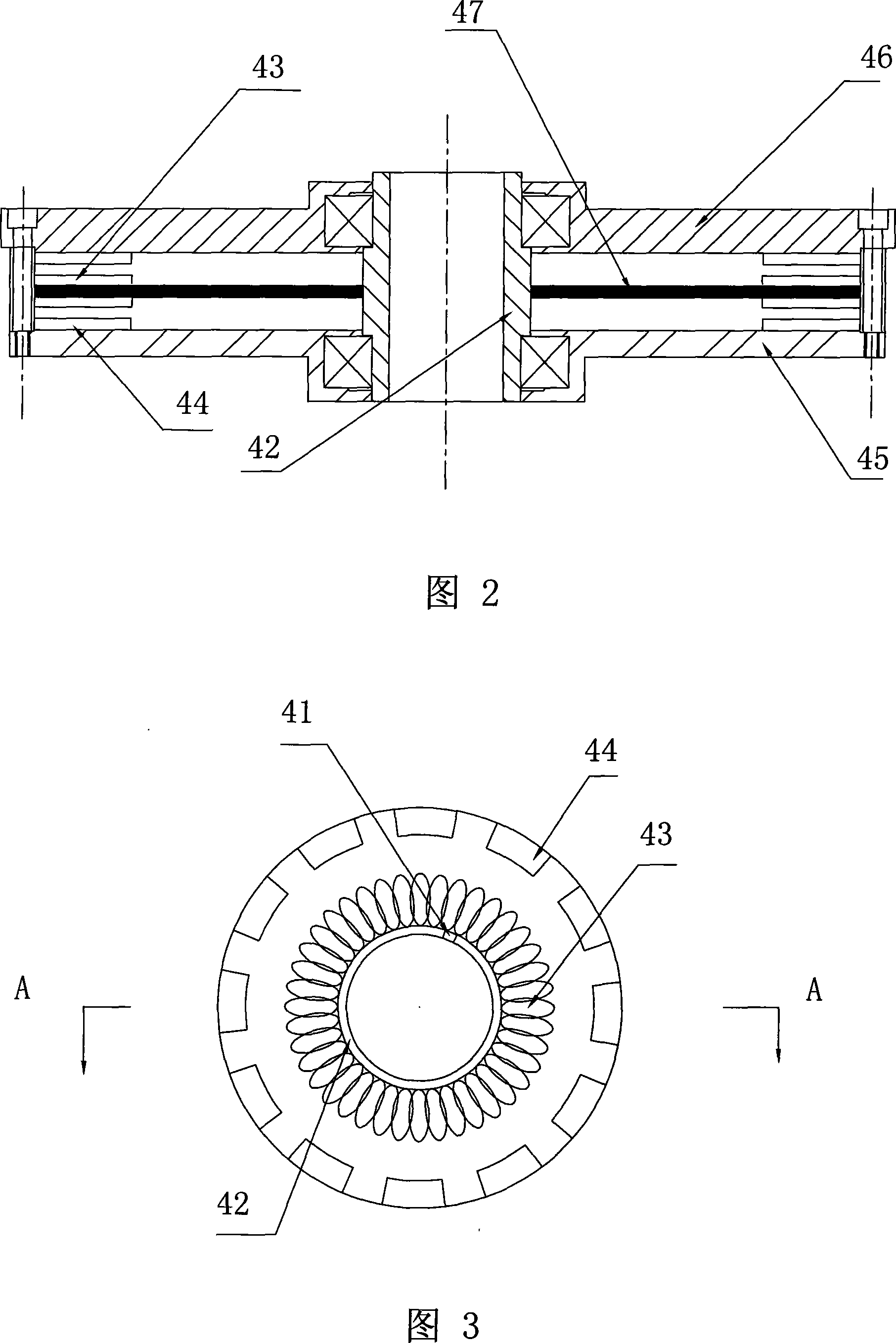
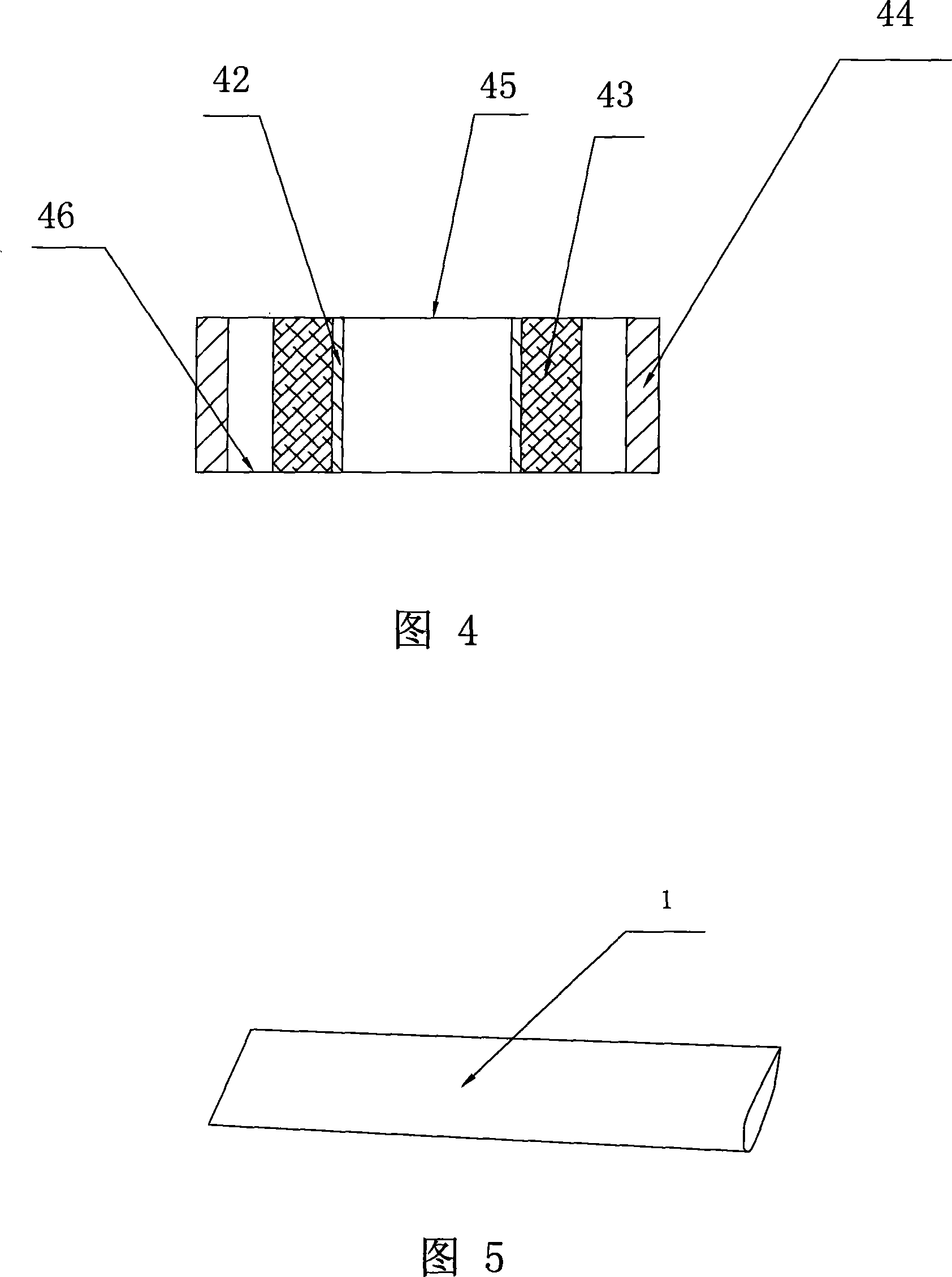
[0077] As shown in FIGS. 3-4 , the motor 4 includes a hollow shaft 42 , a motor upper cover 45 , and a lower cover 46 . The upper cover 45 and the lower cover 46 can rotate around the hollow shaft 42 . The stator and the rotor are disposed between the upper cover 45 and the lower cover 46 . The coil 43 is wound on the outside of the hollow shaft 42 to form a stator; the rotor is a magnetic steel 44 arranged on the outer ring, which can rotate around the hollow shaft 42 with the upper cover 45 and the lower cover 46 . Both the coil 43 and the magnetic steel 44 are arranged coaxially with the hollow shaft 42, and the hollow shaft 42 is provided with a wire groove 41 for extracting electric energy.

[0078] Compared with the prior art, for a motor with the same power, the hollow shaft 42 not only reduces the cost compared to the solid shaft, but also greatly reduces the weight of the motor itse...

Embodiment 3

[0080] As shown in Fig. 1, the blade 1 is made of flexible material, such as high molecular hydrocarbon polymer polylefins, and can be spiral or airfoil. The upper bracket 31, the middle bracket 32 ​​and the lower bracket 33 can all rotate around the longitudinal central axis 2, and the end points of the three brackets are respectively connected with the upper, middle and lower parts of the blade 1, so that the installed three blades 1 can rotate around the longitudinal central axis. 2 Evenly set, and from top to bottom in a spiral or S-shape. Of course, the installed blade 1 can also be straight from top to bottom. Since the blade 1 is a flexible material, it cannot be welded together with the upper bracket 31 , the middle bracket 32 ​​and the lower bracket 33 , and must be fastened through the connecting piece 5 .

[0081] The blade 1 is made of flexible material, so there is no possibility of the blade being broken by strong wind. Therefore, there is no need to take overs...


PUM


Abstract

The invention discloses a wind-driven generator which is provided with a hollow shaft external rotor generator, comprising a longitudinal center shaft, at least one support bracket which can rotate around the longitudinal center shaft, and at least one blade which is connected with the support bracket. The hollow generator is fixedly connected with one of support bracket, the longitudinal center shaft is fixedly connected with the hollow shaft, and the external rotor can rotate to generate electricity as the rotation of the support bracket, thereby not only reducing weight, but also increasing the service life of the generator. Each support bracket of the invention is connected with a shaft sleeve which is sleeved on the outer side of the longitudinal center shaft, the shaft sleeve can be connected or fixedly connected with the support bracket through bolts, the blade is made from soft materials, and the support bracket of the invention also can be connected through a plurality of components in detachable way. With the structure, the wind-driven generator can be installed simply, can be transported detachably, and can reduce transportation costs.

Description

【Technical field】 [0001] The invention relates to a wind power generator, in particular to a wind power generator adopting a hollow shaft external rotor motor. 【Background technique】 [0002] At present, the motors used in wind power generators are basically solid-shaft motors. There are some hollow-shaft motor technologies in the prior art, but they are basically not used in wind power generators. The usual use of wind power generators is still solid-shaft motors. . For example, a British company (the Guietrevolution Ltd) once launched a wind turbine with rotating vertical blades. This design uses three independent S-shaped blades, and the blades are moved from top to bottom through three specially processed triangular fixtures. The shaft is rotated 180 degrees counterclockwise, the motor shaft adopts a solid shaft, and the motor is arranged at the bottom of the whole device. [0003] The disadvantage of using a solid-shaft motor for a wind-driven generator is that the wi...

Claims


Application Information

Patent Timeline
Patent Type & Authority Applications(China)
IPC IPC(8): F03D9/00F03D3/06F03D3/00H02K7/18H02K1/12H02K1/22F03D9/25
CPCY02E10/72Y02E10/74
Inventor 张大鹏胡鹏翔
Owner JIANGSU NEWHOPE RENEWABLE ENERGY S & T
Why Eureka
Try Eureka